Isolating switch

A technology of isolating switches and conductive tubes, which is applied in the direction of electric switches, high-voltage/high-current switches, high-voltage air circuit breakers, etc., and can solve problems such as reduced reliability, poor contact, and shortened service life

Active Publication Date: 2015-01-28
HENAN PINGGAO ELECTRIC +1
View PDF4 Cites 12 Cited by
  • Summary
  • Abstract
  • Description
  • Claims
  • Application Information

AI Technical Summary

Problems solved by technology

However, in the open state, the contact fingers of the dynamic and static main contacts are in the exposed open space, so they are easily affected by the external environment and cause poor contact, especially in environments with high humidity and dust. In this way, the opening

Method used


Image

  • Isolating switch
  • Isolating switch
  • Isolating switch

Examples


Embodiment Construction

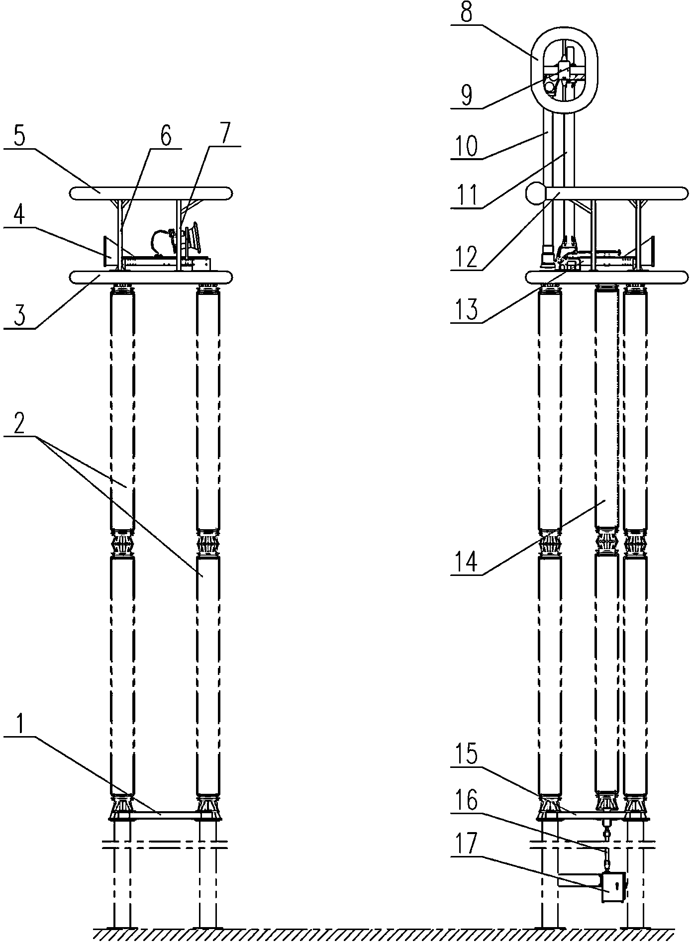
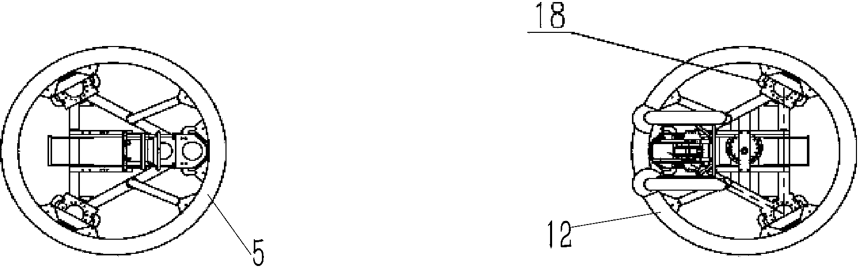
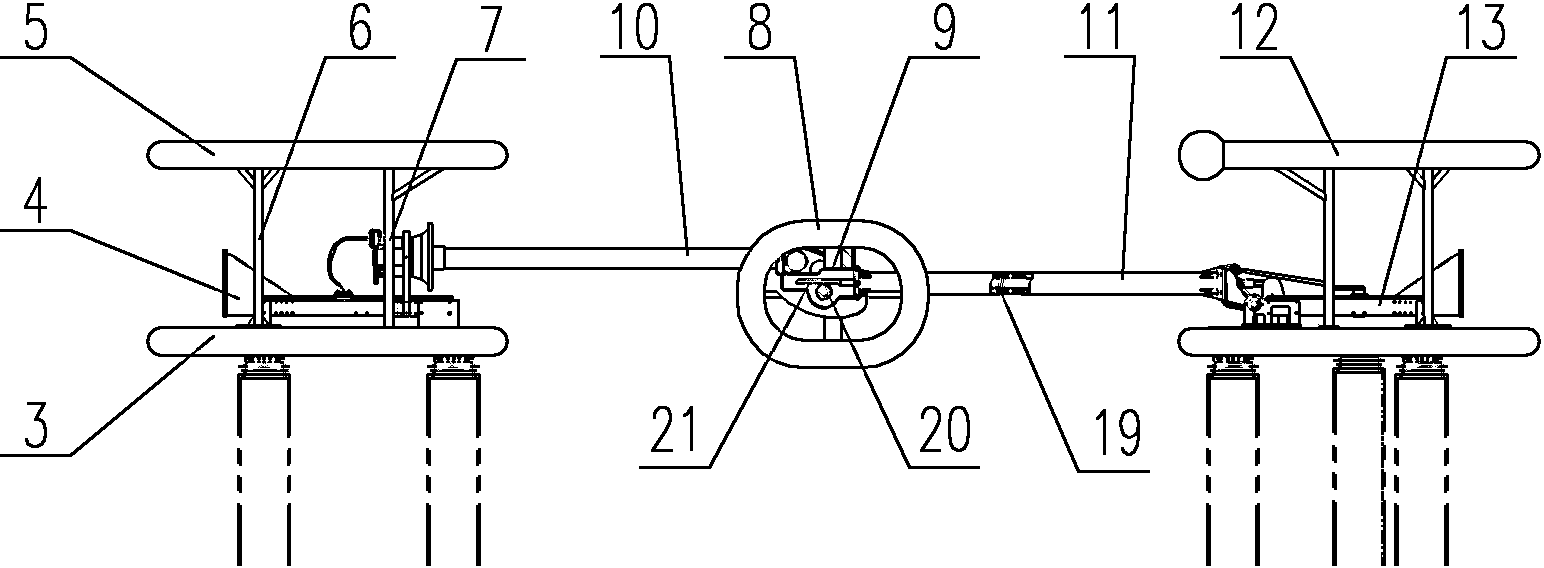
[0018] The embodiment of the isolating switch in the present invention: such as Figure 1 to Figure 5 As shown, the isolating switch is a ±1120kV UHV DC isolating switch, including a dynamic side device and a static side device. The static side device is mainly composed of a static side foundation support 1, a static side support, a static side lower equalizing ring 3, a static side device The contact 4 and the equalizing ring 5 on the static side. The dynamic side device includes an electric operating mechanism 17, a vertical connecting rod 16, a dynamic side base bracket 15, a dynamic side support, a moving side base 13, a dynamic side equalizing ring 12, and Moving contacts. The movable contact includes a rear conductive tube 11, a front conductive tube 10, a movable main contact and a movable arc contact. The movable main contact and the movable arc contact are assembled on the front end of the front conductive tube 10, and the movable main contact is fixed at The ring-sha...


PUM


Abstract

The invention discloses an isolating switch. In the isolating switch, a moving main contact is formed by annular contact fingers which are fixed in a conducting tube or contact fingers which are annularly distributed in the circumferential direction of the conducting tube; a moving arc contact is a contact rod which penetrates into the inner ring of the moving main contact movably and extends front and back, the front end of the contact rod is provided with an arc striking disc, and the rear end of the contact rod is provided with a guide rod segment which is located behind the moving main contact and movably assembled on a guide frame fixed to the inner wall of a guide rod in a front-and-back guide mode; the guide frame is provided with a front supporting wall and a rear supporting wall, the guide rod segment penetrates through the front supporting wall and the rear supporting wall, and the front supporting wall and the rear supporting wall are arranged front and back in a spaced mode; a convex stop shoulder stopped by the front supporting wall is arranged on the periphery of the guide rod segment in a convex mode, and a return spring arranged on the periphery of the guide rod segment in a sleeving mode is arranged between the convex stop shoulder and the rear supporting wall in an abutting mode. In the opening state, part or whole of a forward opening will be sealed by the arc striking disc, so that debris in an outer space is less likely to fall onto the moving main contact through the forward opening of the moving main contact, and the moving main contact is less likely to be corroded by the surroundings in the opening state.

Description

Technical field [0001] The invention relates to an isolating switch. Background technique [0002] According to the “Twelfth Five-Year Plan” of the State Grid Corporation of China, during the “Twelfth Five-Year Plan” period, China will complete the “Zhundong-Chengdu ±1100kV UHV DC Transmission Project”. This transmission line will be the world’s first ±1100kV UHV DC transmission. However, the ±1100kV UHV DC transmission project has not been put into use at home or abroad, and the DC isolating switch equipment that can meet the needs of ±1100kV UHV DC transmission projects has not been developed by manufacturers. Therefore, in order to meet the needs of the project, ± The technical research of 1120kV UHV DC isolating switch has become an important task during the "Twelfth Five-Year Plan" period. [0003] At present, the isolating switch used in high-voltage switchgear is such as the structure disclosed in Chinese Patent Document CN101587787A, which includes a moving contact and a s...

Claims


Application Information

Patent Timeline
IPC IPC(8): H01H33/04H01H33/70
CPCH01H33/12H01H33/70
Inventor 王占杰马永旭孙玉洲徐光辉夏立国王巧红
Owner HENAN PINGGAO ELECTRIC
Why Eureka
Try Eureka