Ultra wide band bridge based on thick film manufacturing technology

A manufacturing process and ultra-broadband technology, applied in the direction of circuits, electrical components, connecting devices, etc., can solve the problems of low-frequency applications of megahertz and below and high-frequency applications above 10GHz, bridge performance constant-ratio power-dividing characteristics and bar It can solve the problems such as the great influence of the thermal balance characteristics, and achieve the effects of high power capacity and antistatic ability, good phase consistency, and high engineering practicability

Inactive Publication Date: 2015-01-28
THE 41ST INST OF CHINA ELECTRONICS TECH GRP
View PDF3 Cites 7 Cited by
  • Summary
  • Abstract
  • Description
  • Claims
  • Application Information

AI Technical Summary

Problems solved by technology

It can be seen that the performance of the bridge is greatly affected by the constant-ratio power-dividing characteristics of the power dividing circuit and the Balun balance characteristics
[0004] At present, the resistive power dividing circuit is mainly a PCB printed board or microstrip circuit technology solution based on lumped parameter components, which is difficult to take into account the needs of low-frequency applications of megahertz and below and high-frequency applications above 10GHz

Method used


Image

  • Ultra wide band bridge based on thick film manufacturing technology
  • Ultra wide band bridge based on thick film manufacturing technology

Examples


Embodiment 1

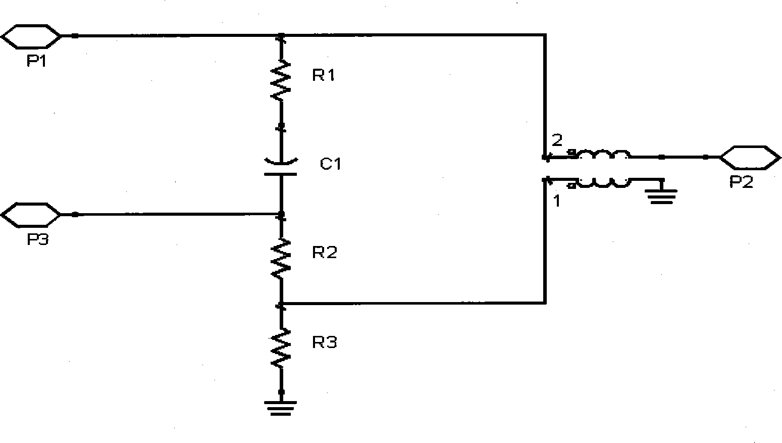
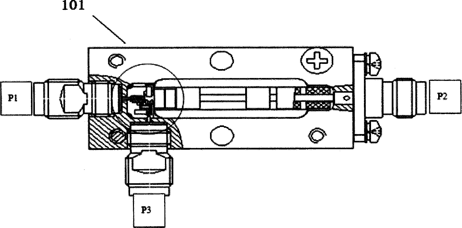
[0019] The present invention provides an ultra-wideband bridge based on a thick film fabrication process, such as figure 2 As shown, it includes a thick-film circuit substrate 101, a coaxial cable, a magnetic core and a capacitor; the ultra-wideband bridge has three external interconnect ports P1, P2, P3, P1 and P3 are two ports connected to the resistance power division circuit. One RF port, P2 is connected to the unbalanced end of the balun; when the signal is transmitted in the forward direction, the P1 port is the input port, after the resistance power division, part of the power is coupled to the P3 port for output, and part of the power is directly output through the P2 port; when the signal is transmitted in the reverse direction At the time, the P2 port is the input port, the signal is converted from unbalanced to balanced by the balun, and two signals of equal amplitude and opposite phase are obtained at the balanced end. To achieve signal isolation, part of the sign...


PUM


Abstract

The invention provides an ultra wide band bridge based on a thick film manufacturing technology. The ultra wide band bridge comprises a thick film circuit substrate, a coaxial cable, a magnetic core and a capacitor. The ultra wide band bridge is externally provided with three mutually connected ports P1, P2 and P3, wherein the port P1 and the port P3 are two radio frequency ports connected to a resistor power distribution circuit and the port P2 is connected to the unbalanced end of a Balun. When signals are transmitted in a non-inverting mode, the port P1 serves as an input port, and after resistor power distribution, partial power is coupled to the port P3 to be output and partial power is directly output through the port P2. When the signals are transmitted in an inverting mode, the port P2 serves as the input port, the signals are converted by the Balun from being unbalanced to being balanced, two routes of signals which are equal in amplitude and opposite in phase are obtained at the balanced end, the two routes of signals are offset at the port P3 through power distribution circuits respectively, signal isolation is achieved for the port P3, and partial power is directly output through the port P1. By the adoption of the ultra wide band bridge based on the thick film manufacturing technology, the applicable frequency of the directional bridge based on the Balun and the resistor power distribution circuit can be improved to be in a millimeter wave band, a larger working bandwidth can be realized, and the ultra wide band bridge is simple in structure and convenient to integrate.

Description

technical field [0001] The invention belongs to the technical field of signal directional separation, and in particular relates to an ultra-wideband electric bridge based on a thick film fabrication process. Background technique [0002] Signal directional separation technology is a key technology in RF microwave systems and testing and measurement. It is widely used in phase shifting, power synthesis and distribution, power sampling, directional coupling, directional detection, and dynamic monitoring of signal sources. The RF microwave circuits or devices that achieve directional separation of signals are mainly directional couplers and directional bridges. The directional coupler of the typical gradient coupling line can realize the directional separation of signals with high directivity in multiple octaves, but when the frequency is lower than 2GHz, the electrical length is long, and the limited coupling line length is difficult to achieve a relatively flat coupling degre...

Claims


Application Information

Patent Timeline
Patent Type & Authority Applications(China)
IPC IPC(8): H01P5/16
Inventor 王飞葛新灵李玉刚
Owner THE 41ST INST OF CHINA ELECTRONICS TECH GRP
Why Eureka
Try Eureka