Lighting test system for display device

A display device and test system technology, applied to static indicators, instruments, etc., can solve problems such as high clock signal frequency, waste, and failure of the test system to complete the test normally, and achieve the effect of improving the scope of application and saving costs

Active Publication Date: 2022-03-25
KUSN INFOVISION OPTOELECTRONICS
View PDF11 Cites 0 Cited by
  • Summary
  • Abstract
  • Description
  • Claims
  • Application Information

AI Technical Summary

Problems solved by technology

[0005] In view of this, the present invention provides a lighting test system for a display device to solve the problem that the clock signal frequency required by the display device is too high and the test system cannot complete the test normally, control the cost of the test system, avoid waste of hardware resources, and realize clock Dynamic conditioning of signals at high frequencies

Method used


Image

  • Lighting test system for display device
  • Lighting test system for display device
  • Lighting test system for display device

Examples


Embodiment Construction

[0027] The present invention is described below based on examples, but the present invention is not limited to these examples. In the following detailed description of the invention, some specific details are set forth in detail. The present invention can be fully understood by those skilled in the art without the description of these detailed parts. In order not to obscure the essence of the present invention, well-known methods, procedures, procedures, components and circuits have not been described in detail.

[0028] The following will clearly and completely describe the technical solutions in the embodiments of the present invention with reference to the accompanying drawings in the embodiments of the present invention. Obviously, the described embodiments are only some, not all, embodiments of the present invention. Based on the embodiments of the present invention, all other embodiments obtained by persons of ordinary skill in the art without creative efforts shall fal...


PUM


Abstract

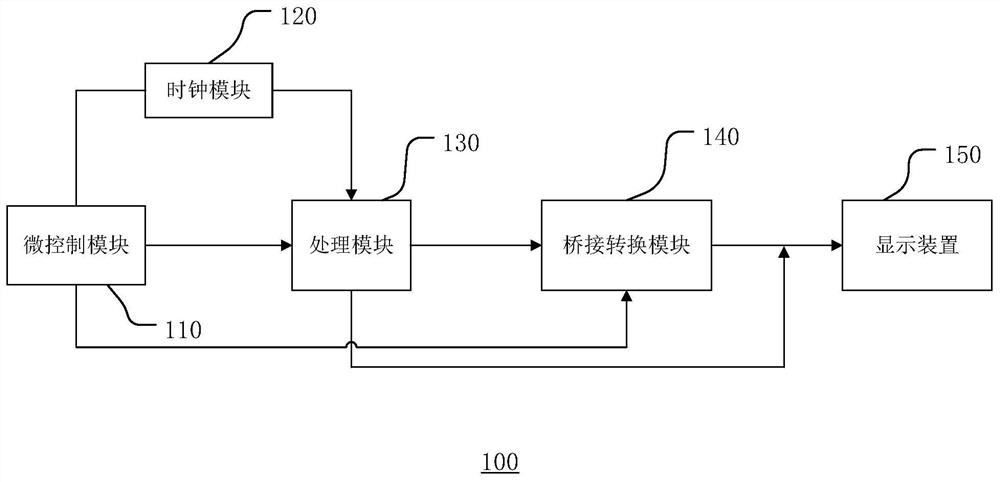
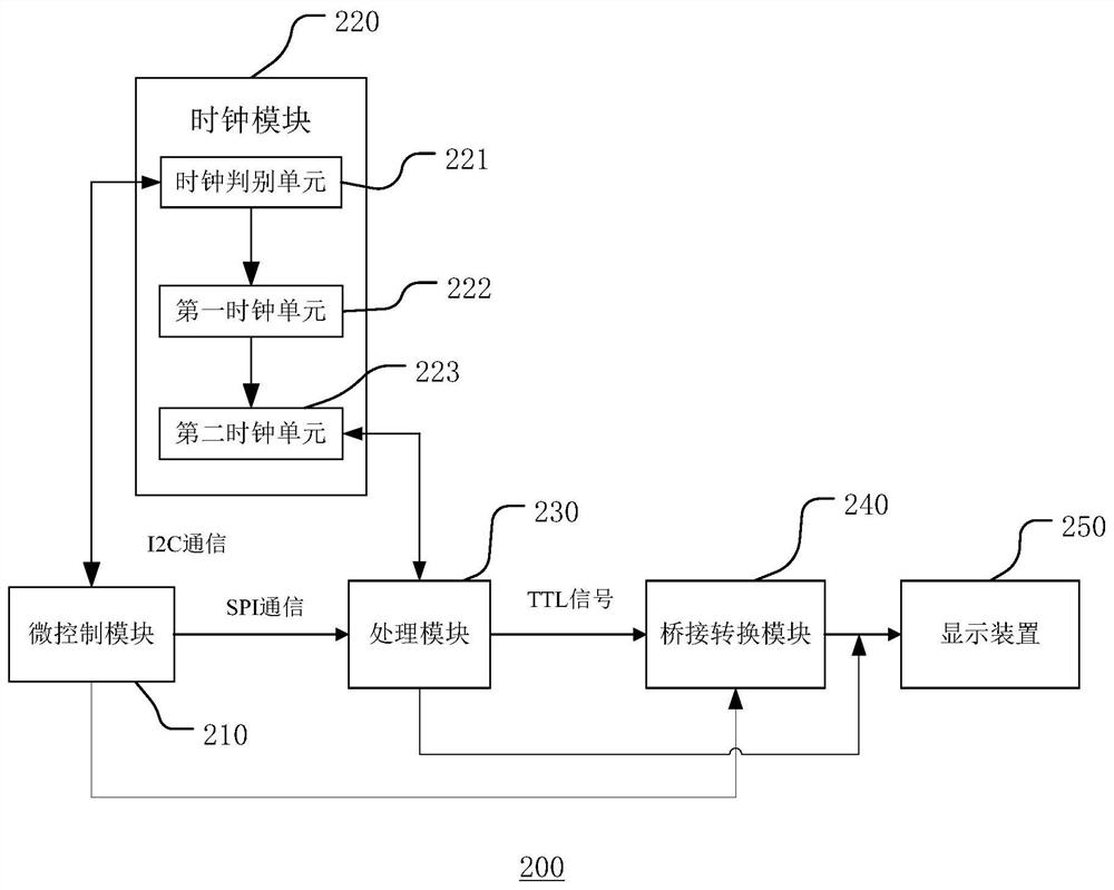
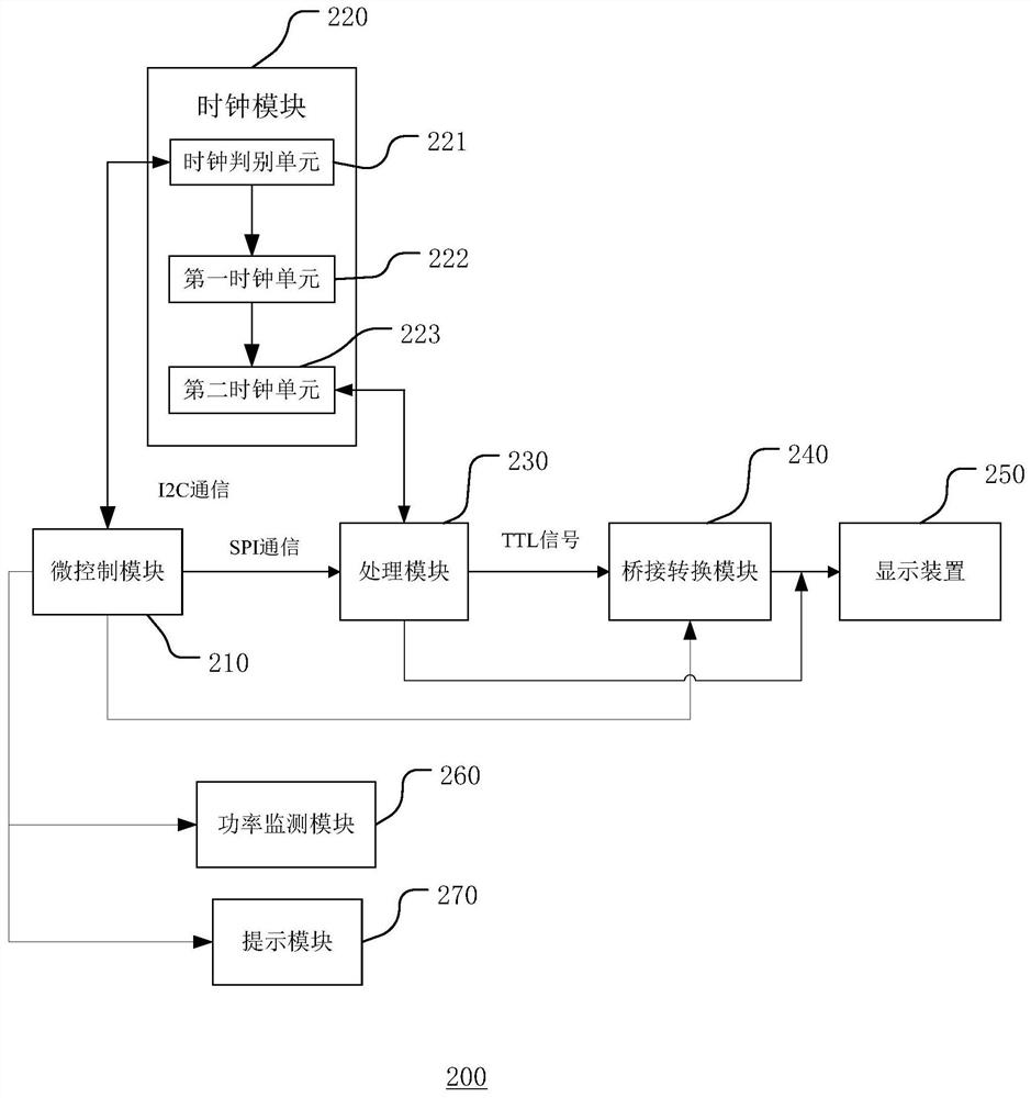
The present application discloses a lighting test system for a display device, including: a micro-control module, a clock module, a processing module, and a bridge conversion module; wherein, the clock module includes a clock discrimination unit, a first clock unit, and a second clock unit, The clock judging unit includes a preset value, and when the frequency of the pixel clock signal exceeds the preset value, the clock judging unit configures the first clock unit to generate a first clock signal, and the second clock unit A pixel clock signal is generated according to the first clock signal. Through the combination of the clock discrimination unit in the clock module and the first clock unit and the second clock unit, the display device lighting test system has a wider applicable frequency range than the original one, so as to solve the problem that the frequency of the clock signal required for lighting exceeds the original When the clock module is at the extreme value, the display device cannot be normally lit to complete the test.

Description

technical field [0001] The invention relates to the technical field of display devices, in particular to a lighting test system for a liquid crystal display device. Background technique [0002] Liquid Crystal Display (LCD for short) has many advantages such as low power consumption, light and thin, low radiation, etc., so it has basically replaced the traditional cathode ray tube (CRT) display now. Currently, liquid crystal display devices are widely used in electronic equipment such as high-definition digital televisions, desktop computers, notebook computers, tablet computers, mobile phones, and digital cameras. [0003] Liquid crystal display devices must pass a lighting test before leaving the factory. The so-called lighting test refers to inputting the timing signals of the liquid crystal display device, the grayscale voltages and data signals of the red, green and blue pixels into the liquid crystal display device to check whether the liquid crystal display device ca...

Claims


Application Information

Patent Timeline
Patent Type & Authority Patents(China)
IPC IPC(8): G09G3/00
CPCG09G3/006
Inventor 赵麟瑄周永超施骏
Owner KUSN INFOVISION OPTOELECTRONICS
Why Eureka
Try Eureka