B-type ultrasonography probe socket

A socket and B-ultrasound technology, which is applied in ultrasonic/sonic/infrasonic diagnosis, medical science, electrical components, etc., can solve problems such as user misplugging, unfavorable protection level, unfavorable shell setting working status indicator, etc., to achieve the structure of the upper shell Simple, improve the effect of EMC protection level and waterproof level

Active Publication Date: 2015-01-28
EDAN INSTR
View PDF7 Cites 8 Cited by
  • Summary
  • Abstract
  • Description
  • Claims
  • Application Information

AI Technical Summary

Problems solved by technology

[0002] The B-ultrasound probe socket is the connection port between the B-ultrasound probe and the B-ultrasound host. The conventional B-ultrasound probe socket uses the left and right two metal shells to assemble the parts required inside. components, and then fixed with screws, the left and right shells in this way are generally symmetrical in appearance, requiring internal components to be fixed on one of the shells, which makes the assembly and fixing of internal functional components consistent with the upper shell. The shape of the shell is very relevant, and it cannot be independent of the upper shell; in addition, the left and right two-lobed shell will leave a long contour gap on the middle mating surface, which is very important for the EMC (electromagnetic compatibility) of the B-ultrasound probe socket. , Electro Magnetic Compatibility) higher protection level requirements are also unfavorable
Moreover, the structure of the left and right two-lobed shell is not conducive to setting the working status indicator on the shell, and the working status of the probe cannot be directly judged from the senses, which may cause the possibility of users pulling out by mistake

Method used


Image

  • B-type ultrasonography probe socket
  • B-type ultrasonography probe socket
  • B-type ultrasonography probe socket

Examples


Embodiment Construction

[0037] In order to make the object, technical solution and advantages of the present invention more clear, the present invention will be further described in detail below in conjunction with the examples. It should be understood that the specific embodiments described here are only used to explain the present invention, not to limit the present invention.

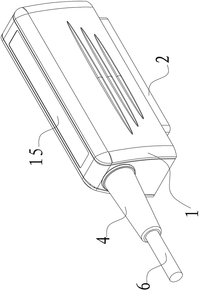
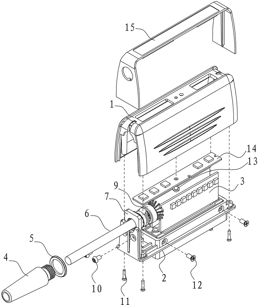
[0038] see Figure 1 to Figure 17 , a B-ultrasound probe socket of the present invention, comprising: a cable 6, a socket circuit assembly 3 and a probe shell;

[0039] The probe housing includes: an upper shell 1 and a bottom plate 2, the upper shell 1 is provided with an indicator light 14, the bottom of the upper shell 1 is provided with a bottom plate installation opening, and the edge 2e of the bottom plate 2 is closely connected to the bottom plate installation opening. In cooperation, the base plate 2 is provided with a socket head accommodating window 2g, and one end of the base plate 2 is provided with a cable...


PUM


Abstract

The invention relates to the field of a medical instrument, and specifically relates to a B-type ultrasonography probe socket. The B-type ultrasonography probe socket mainly comprises a cable, a socket circuit assembly and a probe housing. The probe housing comprises an upper casing and a base plate, the upper casing is provided with an indicating lamp, the bottom of the upper casing is in close fit with the base plate, and the base plate is provided with a first cable port; the socket circuit assembly is arranged in the probe housing; and the first end of the cable is connected with a B-type ultrasonography probe, and the second end of the cable passes through the first cable port to be connected with a circuit board in the socket circuit assembly. According to the invention, the B-type ultrasonography probe socket is arranged by use of a mode of combining the upper casing and the base plate, such that a long-strip-shaped slit in the outer surface of the housing can be prevented, the EMC protection grade and waterproof grade of the product are greatly improved, the upper casing is simple in structure and facilitates arrangement of the indicating lamp, whether the probe works and whether the probe is at a frozen state or a work state can be clearly determined from appearance through the indicating lamp, and the wrong plugging of the probe is prevented during replacement of the probe.

Description

technical field [0001] The invention relates to the field of medical instrument products, in particular to a B-ultrasound probe socket. Background technique [0002] The B-ultrasound probe socket is the connection port between the B-ultrasound probe and the B-ultrasound host. The conventional B-ultrasound probe socket uses the left and right two-petal metal shells to assemble the internal parts required, and then fixes them with screws. In this way, the left and right two-petal shells The shape is generally symmetrical, and the internal parts are required to be fixed on one of the outer shells, which makes the assembly and fixation of the internal functional parts closely related to the shape of the upper shell, which cannot be independent of the upper shell; In addition, the left and right two-piece shell will leave a long contour gap on the middle mating surface, which is also unfavorable for the high EMC (Electro Magnetic Compatibility) protection level requirements of t...

Claims


Application Information

Patent Timeline
Patent Type & Authority Applications(China)
IPC IPC(8): H01R13/502H01R13/717A61B8/00
CPCA61B8/4444H01R13/5202H01R13/6581H01R13/7175
Inventor 罗洪波欧阳波张海峰
Owner EDAN INSTR
Why Eureka
Try Eureka