
Motor base for numerically-controlled machine tool

A technology of CNC machine tools and motor seats, which is applied in the direction of electromechanical devices, electrical components, electric components, etc., can solve the problems of easy loosening and unfavorable normal operation of CNC machine tools, and achieve the problems of avoiding loose components, solving the replacement of electronic seats, and convenient and quick installation Effect

Inactive Publication Date: 2015-01-28
浙江华特数控机床有限公司
View PDF6 Cites 3 Cited by
  • Summary
  • Abstract
  • Description
  • Claims
  • Application Information

AI Technical Summary

Problems solved by technology

During the working process of the motor, due to the vibration of the motor, it is easy to loose some parts of the mounting seat, which is not conducive to the normal work of other components on the CNC machine tool

Method used


Image

  • Motor base for numerically-controlled machine tool
  • Motor base for numerically-controlled machine tool
  • Motor base for numerically-controlled machine tool

Examples


Embodiment Construction

[0010] The present invention will be further described below in conjunction with drawings and embodiments.

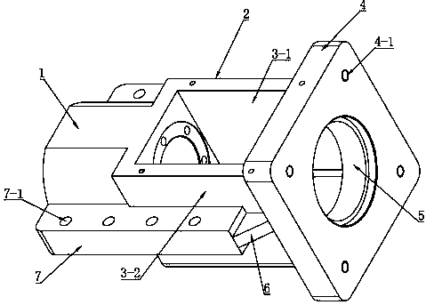
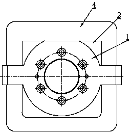
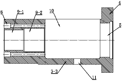
[0011] Such as figure 1 , figure 2 and image 3 As shown, the present invention includes a shaft hole seat 1 , an installation seat 2 and a base 4 in order from left to right. The shaft hole seat 1, the mounting seat 2 and the base 4 are integrally formed structures.

[0012] The shaft hole seat 1 is a cylindrical structure, and the inner ring is provided with stepped shaft holes, which are respectively the first-level shaft hole 9-1 and the second-level shaft hole 9-2, and the diameter of the first-level shaft hole 9-1 is less than The diameter of the second-stage shaft hole 9-2. Counterbore holes 8 with the same interval angle are distributed around the shaft hole, and the counterbore holes 8 run through both ends of the shaft hole seat 1 .

[0013] The mounting seat 2 is a square seat, and its three sides are enclosed by the side plate 3-1, the side plate 3-2 a...


PUM


Abstract

The invention discloses a motor base for a numerically-controlled machine tool. The motor base sequentially comprises a shaft hole seat, an installation seat and a base from left to right, wherein the shaft hole seat, the installation seat and the base are of an integrally-formed structure. The shaft hole seat is of a cylindrical structure, and stair-stepping shaft holes including a first-step shaft hole and a second-step shaft hole are formed in the inner ring. The installation seat is a square seat, the three surfaces of the installation seat define an installation groove through lateral plates, a square opening is formed in one surface of the installation seat, and the two ends of the installation groove are connected with the shaft hole seat and the base respectively. A square plate serves as the base, and a round through hole is formed in the middle of the square plate. Installation side plates are arranged on the outer surfaces of the shaft hole seat and the installation seat, and reinforcement ribs are arranged between the installation side plates and the base. Integrated design is adopted in the motor base, so that installation of an assembly of the motor base is omitted, and the motor base has the advantage of convenient and rapid installation.

Description

technical field [0001] The invention relates to the field of motor accessories, in particular to a motor base for a numerically controlled machine tool. Background technique [0002] Due to the different types of motors used in the existing CNC machine tools, the structural design of the mounting base is also different. Once the type of motor needs to be replaced, the mounting base must also be replaced. Because the mounting seat is installed on the numerical control machine tool, and the existing mounting seat is assembled from various parts, and there are many parts, it is very troublesome to disassemble and install. During the working process of the motor, due to the vibration of the motor, it is easy to loose some parts of the mounting seat, which is not conducive to the normal operation of other components on the CNC machine tool. Contents of the invention [0003] The purpose of the present invention is to provide a numerically controlled machine tool motor bas...

Claims


Application Information

Patent Timeline
Patent Type & Authority Applications(China)
IPC IPC(8): H02K5/26H02K5/20
CPCH02K5/00H02K5/20
Inventor 胡经丰
Owner 浙江华特数控机床有限公司
Learn More