A sleeve-sliding friction nanogenerator

A nano-generator and generator technology, applied in the direction of friction generators, etc., can solve the problems of large size, complex structure, and inability to use power supply components of micro-electronic devices, etc., to expand the scope of application, improve output power, package Technically convenient effects

Active Publication Date: 2016-03-30
BEIJING INST OF NANOENERGY & NANOSYST
View PDF4 Cites 2 Cited by
  • Summary
  • Abstract
  • Description
  • Claims
  • Application Information

AI Technical Summary

Problems solved by technology

These generators all require relatively concentrated and high-intensity energy input, and it is basically impossible to effectively convert the kinetic energy of low intensity generated in people's daily activities and existing in nature into electrical energy.
At the same time, traditional generators are large in size and complex in structure, and cannot be used as power supply components for microelectronic devices at all.

Method used


Image

  • A sleeve-sliding friction nanogenerator
  • A sleeve-sliding friction nanogenerator
  • A sleeve-sliding friction nanogenerator

Examples


Embodiment 1

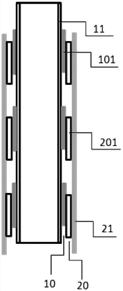
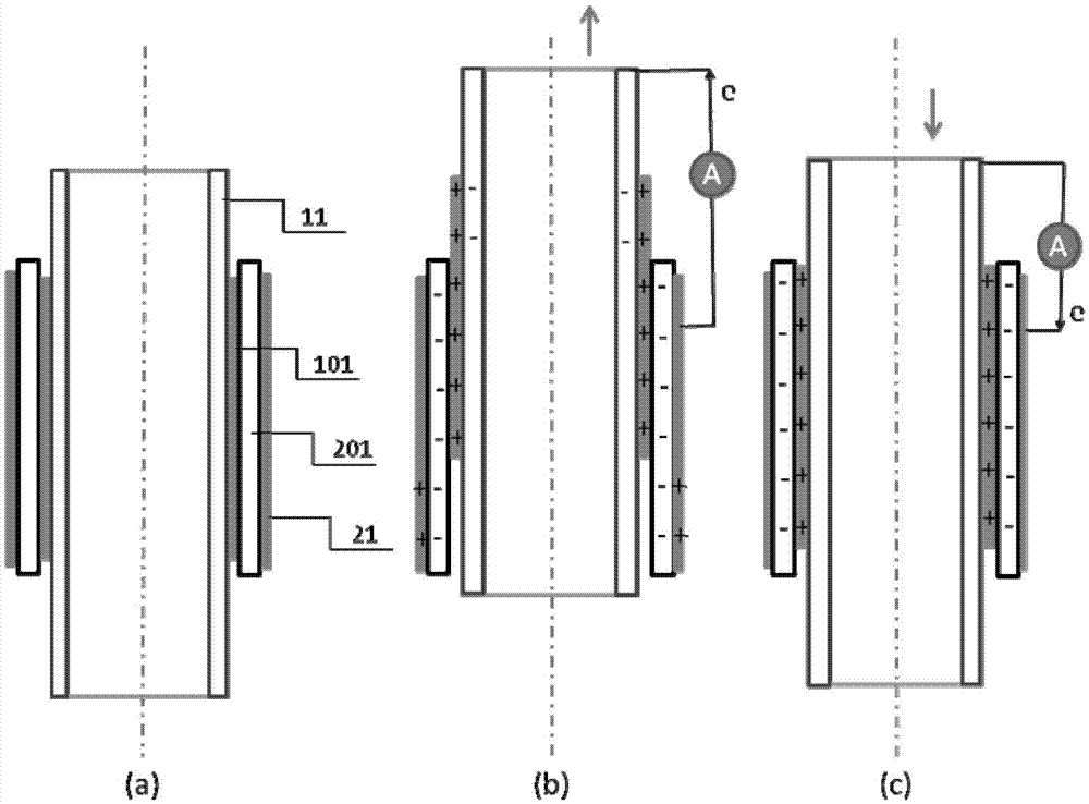
[0116] The first conductive element is a metal copper sheet with a size of 6.4cm×3.8cm, the second conductive element is a metal aluminum sheet with a size of 6.4cm×4.5cm, and the material of the first friction unit is Teflon (polytetrafluoroethylene) film. The material of the second friction unit is polyethylene terephthalate (PET). Polytetrafluoroethylene and polyethylene terephthalate have extremely negative and extremely positive polarities, respectively, in the triboelectric series. Teflon is made into two strip film structures with length, width and height of 6cm, 1.6cm and 0.2cm respectively, and according to Image 6 In the same way, the conductive glue is pasted on the copper sheet at intervals, and the polyethylene terephthalate is distributed on the aluminum sheet with the same size and interval. Roll the copper sheet pasted with Teflon into a cylinder around a plastic rod with a diameter of about 0.6cm and a length of 10cm and fix the two ends with adhesive strips...

Embodiment 2

[0119] This embodiment is basically the same as Embodiment 1, the only difference is that: a silicon wafer with a thickness of 600 μm is used as the second friction unit material, and a layer of photoresist is coated on the surface of the silicon wafer by rotation A square window array with a side length of micron or sub-micron level is formed on the glue, and the silicon wafer after photolithography is chemically etched with hot potassium hydroxide to form a pyramid-shaped concave structure array at the window. Then divide it into small pieces with a length of 2 cm and a width of 2 cm, and arrange them on the surface of the second conductive element in a checkerboard shape; The pattern of the same checkerboard-shaped Ag thin layer, the thin layer also serves as the first conductive element. When the silicon chip and the two materials of Ag are in contact with each other under the action of external force and relatively slide, because the surface of the silicon chip has a conc...

Embodiment 3

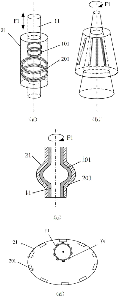
[0121] This embodiment is basically the same as Embodiment 1, the difference is that firstly through conventional methods such as mask-etching-metal deposition-mask removal, a hexagonal polychloride sleeve is formed such as Figure 5 For the annular gold Au strip shown, the width of the strip along the axial direction is about 100 μm. Then continue to prepare polydimethylsiloxane (PDMS) ring strips on the top of the gold strips by spin coating and etching as the first friction unit, and further prepare nanowire arrays on the surface by inductively coupled plasma etching , the specific steps are: deposit about 10 nanometers of gold on the surface of PDMS with a sputtering device, then put the PDMS film into an inductively coupled plasma etching machine, etch the side where the gold is deposited, and pass through O 2 , Ar and CF 4 Gas, the flow rate is controlled at 10sccm, 15sccm and 30sccm respectively, the pressure is controlled at 15mTorr, the working temperature is control...


PUM


Abstract

A jacketed sliding frictional nano generator which comprises a first conducting element (11), a first frictional layer (10) which is placed in contact with the outer surface of the first conducting element, a second conducting element (21), and a second frictional layer (20) which is placed in contact with the inner surface of the second conducting element, wherein the first frictional layer comprises a plurality of first frictional units (101) and the second frictional layer comprises a plurality of second frictional units (201); moreover, the outer surfaces of all the first frictional units belong to a first curved surface; the inner surfaces of all the second frictional units belong to a second curved surface; the first curved surface and the second curved surface outside the first curved surface form an inner and outer jacketed structure; the outer surfaces of the first frictional units and the inner surfaces of the second frictional units generate relative sliding friction; meanwhile, the frictional area is changed; and an electrical signal is output to an outer circuit through the first conducting element and the second conducting element. The frictional nano generator can be used as a new energy technology or a sensing technology.

Description

technical field [0001] The invention relates to a generator, in particular to a sheath-sliding friction nanometer generator which converts the mechanical energy of applied external force into electrical energy. Background technique [0002] Today, with the rapid development of microelectronics and material technology, a large number of new microelectronic devices with multiple functions and high integration have been developed continuously, and have shown unprecedented application prospects in various fields of people's daily life. However, the research on the power supply system matched with these microelectronic devices is relatively lagging behind. Generally speaking, the power supply of these microelectronic devices all comes from batteries directly or indirectly. Batteries are not only large in size and heavy in weight, but also contain toxic chemical substances that are potentially harmful to the environment and the human body. Therefore, it is of great significance t...

Claims


Application Information

Patent Timeline
Patent Type & Authority Patents(China)
IPC IPC(8): H02N1/04
CPCH02N1/04
Inventor 王中林
Owner BEIJING INST OF NANOENERGY & NANOSYST
Why Eureka
Try Eureka