Two-dimensional display mode and three-dimensional display mode switchable display device and method

A technology of three-dimensional display and mode switching, which is applied in the direction of optics, instruments, electrical components, etc., to achieve the effect of reducing costs

Inactive Publication Date: 2015-01-28
XIDIAN UNIV
View PDF5 Cites 1 Cited by
  • Summary
  • Abstract
  • Description
  • Claims
  • Application Information

AI Technical Summary

Problems solved by technology

It can be seen that the existing 3D display technology cannot completely replace the traditional 2D display technology.

Method used


Image

  • Two-dimensional display mode and three-dimensional display mode switchable display device and method
  • Two-dimensional display mode and three-dimensional display mode switchable display device and method

Examples


Embodiment 1

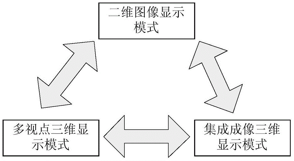
[0060] Embodiment 1: Switch the two-dimensional image display mode to the multi-viewpoint three-dimensional display mode.

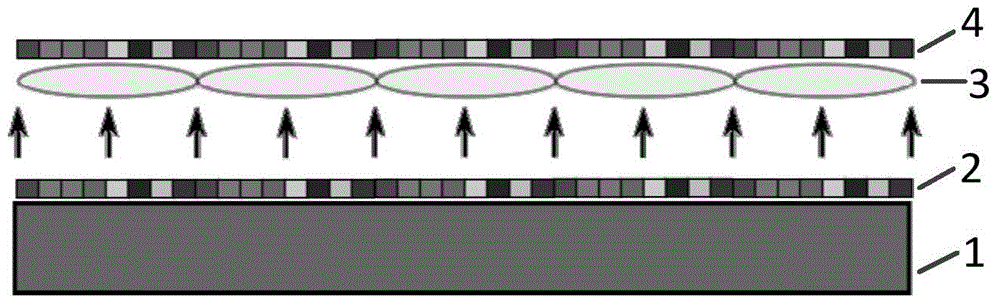
[0061] Step A. Dividing the built-in liquid crystal layer 3 into sub-regions corresponding to the individual lenses in the lens array 4 to obtain 33*27 orthogonally arranged sub-region arrays.

[0062] Step B. Set the left half of the pixels in each sub-region to the light-transmitting state, and the right half of the pixels to the light-shielding state, so that the built-in liquid crystal layer 3, the backlight source 1 and the lens array 4 form the directivity of the parallax image of the right viewpoint Backlight source: switch the external liquid crystal layer 2 from displaying two-dimensional images to displaying right viewpoint parallax images.

[0063] Step C. Set the right half of the pixels in each sub-region to the light-transmitting state, and the left half of the pixels to the light-shielding state, so that the built-in liquid crystal layer 3,...

Embodiment 2

[0065] Embodiment 2: Switching the two-dimensional image display mode to the integrated imaging three-dimensional display mode.

[0066] Step E. The computer changes the voltage value of each pixel in the external liquid crystal layer 3 through the video signal, and switches the external liquid crystal layer 2 from displaying two-dimensional images to a light-transmitting state, so that it has no modulation effect on light.

[0067] Step F. The light emitted by the backlight source 1 is modulated into a unit image array through the built-in liquid crystal layer 3, and then deflected by the lens array 4 to realize an integrated imaging three-dimensional display mode.

Embodiment 3

[0068] Embodiment 3: Switching the multi-view point three-dimensional display mode to the two-dimensional image display mode.

[0069] Step G. The computer changes the voltage value of each pixel in the external liquid crystal layer 3 through the video signal, and sets the built-in liquid crystal layer 3 to a light-passing state so that it has no modulation effect on light;

[0070] Step H. The light emitted by the backlight source 1 passes through the built-in liquid crystal layer 3 and the lens array 4 to generate non-directional uniform light, which provides backlight for the external liquid crystal layer 2, and the computer changes and loads each element in the external liquid crystal layer 2 through video signals. The voltage signal on the pixel switches the external liquid crystal layer 2 from the light-transmitting state to displaying a two-dimensional image, thereby realizing a two-dimensional image display mode.


PUM


Abstract

The invention discloses a two-dimensional display mode and three-dimensional display mode switchable device and method. The problem that an existing display device is simple in display mode is mainly solved. The two-dimensional display mode and three-dimensional display mode switchable device comprises a backlight source (1), a built-in liquid crystal layer (3), an external liquid crystal layer (2) and a lens array (4). When the built-in liquid crystal layer is in an all-pass state, the backlight source, the built-in liquid crystal layer and the lens array form a new backlight source, and light intensity is modulated through the external liquid crystal layer to achieve two-dimensional image display. The built-in liquid crystal layer, the backlight source and the lens array form a directional backlight source, and a two-dimensional anaglyph is displayed through the external liquid crystal layer to achieve multi-view three-dimensional display. When the external liquid crystal layer is in the all-pass state, unit image arrays are displayed through the built-in liquid crystal layer to achieve integrated imaging three-dimensional display. The two-dimensional display mode and three-dimensional display mode switchable device and method can achieve free switching of two-dimensional image display, multi-view three-dimensional display and integrated imaging three-dimensional display and can be used for display of televisions, computers and the like.

Description

technical field [0001] The invention belongs to the technical field of image display, and more specifically relates to a mode switching device and method between two-dimensional image display and three-dimensional image display, which can be used for TV, computer and hand-held display. Background technique [0002] At present, the resolution of two-dimensional display can reach high definition, but the displayed image is a flat image, which lacks depth information. Multi-viewpoint 3D display technology belongs to 3D display technology, which can display multiple plane parallax images, the corresponding parallax images are received by both eyes, and the 3D effect can be produced through brain fusion. The principle of the multi-viewpoint display technology is simple, and the resolution of the displayed image is high. Using directional backlight technology and time-division multiplexing technology, the image resolution of multi-viewpoint display is comparable to that of a two-...

Claims


Application Information

Patent Timeline
Patent Type & Authority Applications(China)
IPC IPC(8): H04N13/00G02B27/22
Inventor 王晓蕊张建磊杜军辉马琳刘鑫黄曦刘德连张建奇
Owner XIDIAN UNIV
Why Eureka
Try Eureka