Fast positioning and disassembling device for testing mechanical performance of optical cable

A technology of mechanical properties and optical cables, applied in the field of new devices, can solve the problems of optical cable damage, clamping force, difficulty in accurate control, small friction, etc., to reduce impact and noise, reduce operating time, and prolong service life.

Active Publication Date: 2015-02-04
JIANGSU HENGTONG PHOTOELECTRIC
View PDF6 Cites 5 Cited by
  • Summary
  • Abstract
  • Description
  • Claims
  • Application Information

AI Technical Summary

Problems solved by technology

After the test is over, first screw the bolt back, hold the metal sleeve, open the clamp, peel off the cloth, and take out the optical cable. The operation is cumbersome
When adjusting the bolt to control the friction force, it depends entirely on the subjective judgment of the operator, which is not easy to control accurately, and may cause damage to the optical cable or insufficient clamping force, causing the optical cable to move axially
At the same time, because the replaceable sleeve inside the fixing device is m

Method used


Image

  • Fast positioning and disassembling device for testing mechanical performance of optical cable
  • Fast positioning and disassembling device for testing mechanical performance of optical cable
  • Fast positioning and disassembling device for testing mechanical performance of optical cable

Examples


Embodiment Construction

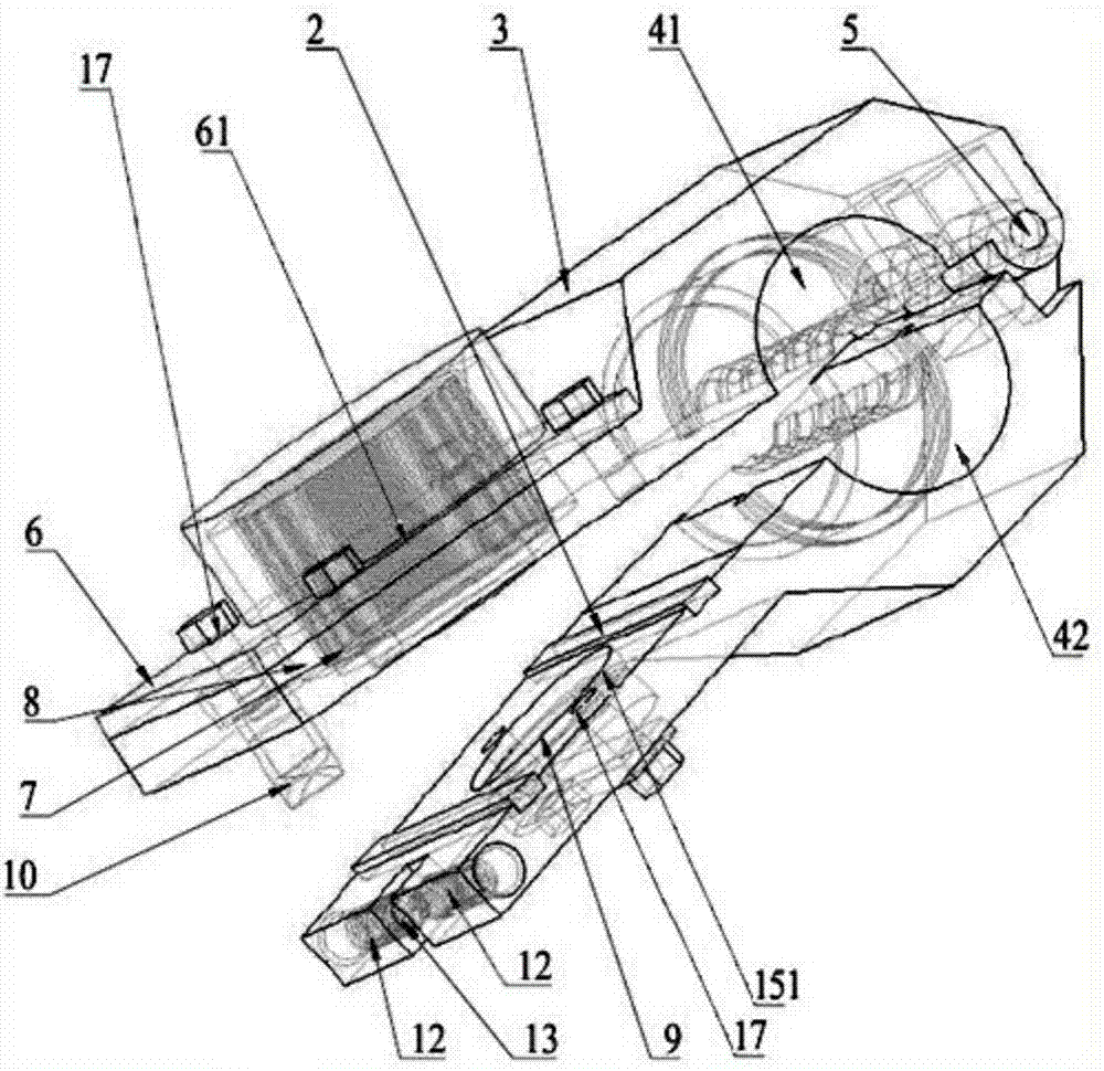
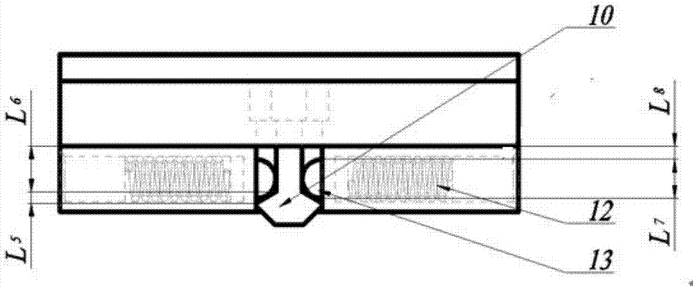
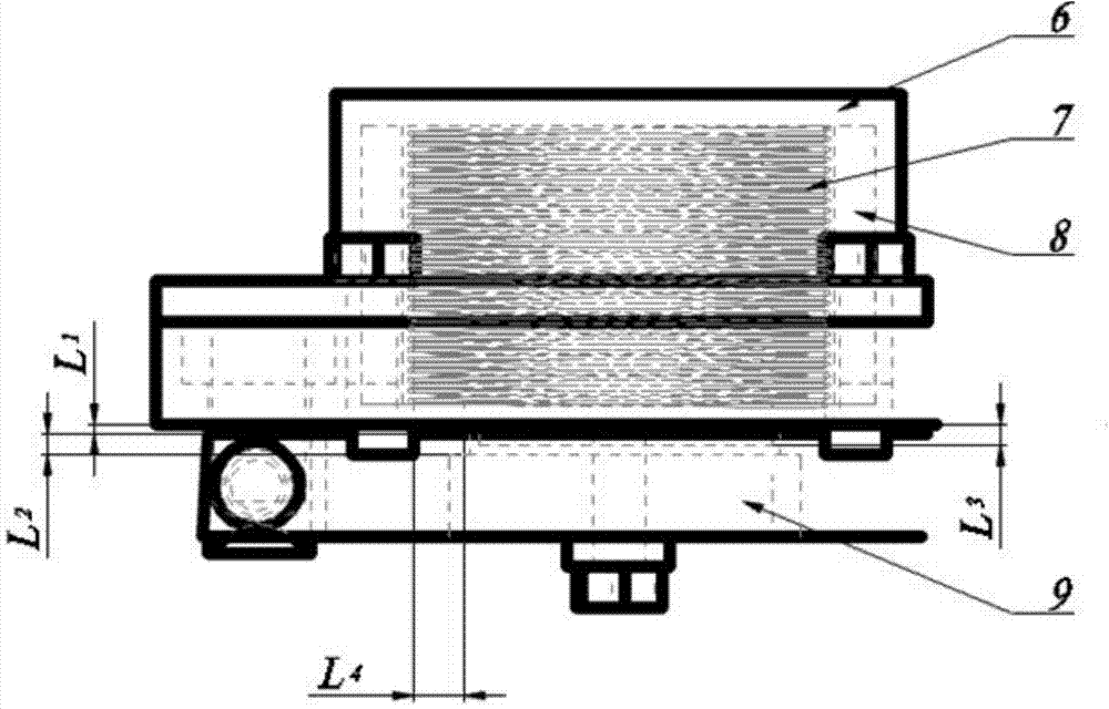
[0026] Such as figure 1 As shown, a quick positioning and unloading device for testing the mechanical properties of optical cables includes an upper splint 3, a lower splint 15, a splint connecting shaft pin 5, a sleeve for clamping optical cables, an electromagnetic automatic switch, and a self-locking device , the electromagnetic automatic switch includes an electromagnet 7, a permanent magnet 9, an electromagnet sleeve 8 and a cover plate 6, the electromagnet 7 is composed of a coil and an iron core, and the self-locking device includes a hook 10, a spring 12, and a dead bolt 13, The sleeve is divided into an upper semicircle sleeve 41 and a lower semicircle sleeve 42. The upper splint 3 is connected to the lower splint 15 through the pivot pin 5 of the splint. The upper semicircle sleeve 41 is detachably connected with the upper splint 3. The lower semicircle sleeve 42 is connected The lower splint 15 is detachably connected, the cover plate 6 is located in the upper splin...


PUM


Abstract

The invention relates to a fast positioning and disassembling device for testing the mechanical performance of an optical cable. The fast positioning and disassembling device comprises an upper clamping plate, a lower clamping plate, a clamping plate connecting shaft pin, a sleeve for clamping the optical cable, an automatic electromagnetic opening and closing device and a self-locking device, wherein the automatic electromagnetic opening and closing device comprises an electromagnet, a permanent magnet, an electromagnet sleeve and a cover plate; the self-locking device comprises a clamping hook, springs and a locking tongue; the sleeve is divided into an upper semicircular sleeve and a lower semicircular sleeve; the upper clamping plate is rotatably connected with the lower clamping plate by the clamping plate connecting shaft pin; the upper semicircular sleeve is connected with the upper clamping plate in a detachable manner; the lower semicircular sleeve is connected with the lower clamping plate in a detachable manner; the cover plate is positioned in the upper clamping plate; the electromagnet is fixed in the electromagnet sleeve which is fixed in the upper clamping plate by the cover plate; the permanent magnet is fixed in the lower clamping plate; the clamping hook is fixed in the upper clamping plate; the locking tongue is positioned in the lower clamping plate; and the springs are positioned at the two sides of the locking tongue. The fast positioning and disassembling device provided by the invention has the advantages that the optical cable is effectively protected, the working efficiency is high and the safety is high.

Description

technical field [0001] The invention relates to the fields of mechanical engineering and optical communication, and proposes a novel device for fast positioning, clamping and loosening of optical cables. Background technique [0002] Optical cables are manufactured to meet optical, mechanical or environmental performance specifications, using one or more optical fibers placed in a sheath as a transmission medium, and used individually or in groups. Communication cable assemblies. The optical cable is generally composed of several parts such as a cable core, a reinforced steel wire, a filler, and a sheath. In addition, there are components such as a waterproof layer, a buffer layer, and an insulated metal wire as required. [0003] The fixing device of the optical cable is used to clamp the optical cable to prevent the axial movement of the optical cable during tensile, torsion and other mechanical performance tests. It first applies pressure to the outer sheath of the optic...

Claims


Application Information

Patent Timeline
IPC IPC(8): B25B11/00
CPCB25B11/002
Inventor 邓超尹纪成薛梦驰袁丰洪润周牧青
Owner JIANGSU HENGTONG PHOTOELECTRIC
Why Eureka
Try Eureka