

A step-by-step pressurized fuel tank
A technology for pressurizing fuel tanks and fuel tank bodies, which is applied to fuel supply tank devices, fluid pressure converters, fluid pressure actuating devices, etc. The problem of short effective boosting stroke of the oil pressure tank, etc., achieves the effect of increasing the effective stroke, good oil storage, and good environmental adaptability
- Summary
- Abstract
- Description
- Claims
- Application Information
AI Technical Summary
Problems solved by technology
Method used
Image

Examples
Embodiment Construction
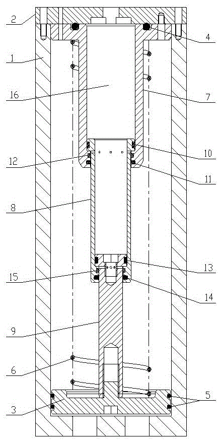
[0011] A step-by-step pressurized fuel tank, including: fuel tank body 1, fuel tank cover 2, booster piston 3, O-ring seal 4, piston seal 5 and spring 6, and also includes: push rod housing 7, a first-stage push rod 8. Secondary push rod 9, guide ring A10, piston rod seal A11, guide ring B12, guide ring C13, piston rod seal B14 and guide ring D15. The push rod housing 7 has a stepped through hole in the axial direction. One end of the push rod housing 7 is a flange, and the outer end surface of the flange has a sealing groove. There are piston rod sealing grooves and piston rod guide grooves in turn. The first-stage push rod 8 has a stepped through hole in the axial direction, and there is a groove on the outer surface of one end of the first-stage push rod 8, and the inner wall of the through hole at the other end has a piston rod sealing groove and a piston rod guide in turn from the end surface. groove. Grooves are arranged on the outer surface of the secondary push rod 9...
PUM
 Abstract
Description
Claims
Application Information