
Retarder with improved bearing lubrication

A retarder and machine technology, applied in the field of hydraulic machines, can solve the problem that the oil cannot reach the bearing parts reliably

Active Publication Date: 2015-02-04
VOITH PATENT GMBH
View PDF6 Cites 0 Cited by
  • Summary
  • Abstract
  • Description
  • Claims
  • Application Information

AI Technical Summary

Problems solved by technology

Although there is always a residual amount of oil in the retarder, it is only used to reduce idling resistance, and this oil cannot reliably reach the bearing parts

Method used


Image

  • Retarder with improved bearing lubrication
  • Retarder with improved bearing lubrication
  • Retarder with improved bearing lubrication

Examples


Embodiment Construction

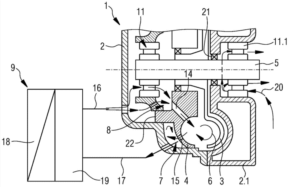
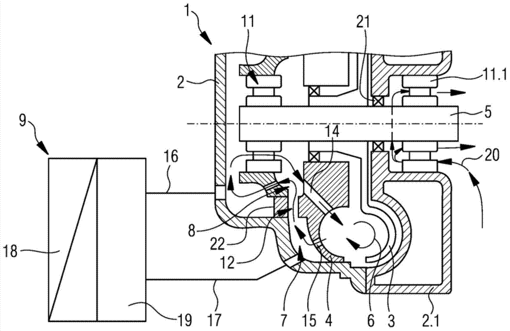
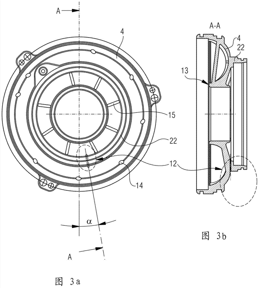
[0025] figure 1 The retarder 1 without connecting channels is shown in braking mode. The working medium is supplied to the inlet region 8 from the external working medium circuit 9 . Oil enters the working space between rotor 3 and stator 4 from inlet region 8 via inlet channel 14 provided here in stator 4 . If the working medium, for example oil, is present in the working space, a braking torque is generated by the retarder, whereby the oil is heated. For cooling purposes, through the pumping action of the retarder, always a partial amount of working medium is pumped back into the external working medium circuit 9 through outlet openings 15 provided here in the stator 4 .

[0026] The external working medium circuit 9 essentially consists of a working medium accumulator 19 to which compressed air can be applied and a cooler 18 . During braking operation, the working medium accumulator 19 is supplied with compressed air, so that working medium enters the retarder 1 or the w...


PUM


Abstract

The invention relates to a hydraulic machine and specifically a hydraulic retarder (1) which comprises a retarder shell body (2), a rotor (3) and a stator (4), wherein the rotor (3) and the stator (4) form an annular working space (5), the working space is connected with a working medium from an external working medium return circuit (9) through an inlet area (8) and an outlet area (7) according to the working state of the machine, the rotor (3) is arranged on a shaft (10) which can be supported in a rotating manner, and at least one side of the shaft is supported in the retarder shell body (2) through a bearing (11). To improve operation safety in non-braking operation, a connecting passageway (12) is arranged between the outlet area (7) and the inlet area (6), at least in the non-braking operation, the working medium used for lubricating the bearing (11) can pass through the connecting passageway in a flowing manner, and the bearing can be lubricated and / or cooled enough.

Description

technical field [0001] The invention relates to a hydraulic machine, especially a hydraulic retarder. Background technique [0002] The retarder basically includes a retarder housing, a bladed rotor and a bladed stator, wherein the rotor and the stator form a torus-shaped working space with each other. It is connected with the working medium from the external working medium circuit through the inlet area and the outlet area according to the working state of the machine. [0003] The rotor is provided on a rotatably supported shaft, at least one side of which is supported inside the retarder housing via bearings. [0004] Such hydrodynamic machines or retarders are commercially available in numerous variants or are known from numerous publications. Oil is the working medium, and water with different mixtures can also be considered as the working medium. [0005] Some variants are configured such that the bearing of the retarder shaft is arranged inside the retarder housing...

Claims


Application Information

Patent Timeline
Patent Type & Authority Applications(China)
IPC IPC(8): F16D57/00
CPCF16D2300/0214F16D57/04F16D33/18B60T10/02F16D33/06
Inventor V.博加特金D.劳克曼
Owner VOITH PATENT GMBH
Learn More