Digital trusted instrument with CAN interface

A technology of receiver and interface, applied in the field of servo system, can solve the problems of easy interference, too long excitation power supply line, difficult measurement, etc., to reduce the workload of debugging, reduce the workload of calculation, and facilitate the inspection and acceptance.

Inactive Publication Date: 2015-02-04
中国兵器工业第二〇二研究所
View PDF8 Cites 3 Cited by
  • Summary
  • Abstract
  • Description
  • Claims
  • Application Information

AI Technical Summary

Problems solved by technology

[0004] 1) The accuracy of the excitation power supply of the self-aligning machine (or resolver) directly affects the accuracy of angle measurement, and the excitation power supply line is too long, which is prone to interference and affects the accuracy
[0005] 2) The output 3-phase AC analog signal, because the output analog signal power is small, the transmission distance is long, the deformation is serious, and the accuracy is affected
[0007] 4) It is necessary to perform rough and fine combined calculations inside the servo controller, which increases the calculation workload of the servo control computer
[0008] 5) Coarse and fine corrections to zero are required in the combined calculation of coarse and fine, which increases the debugging workload of the servo control computer
[0009] 6) The receiver only realizes part of the functions of the sensor, it is difficult to check and accept the accuracy, and it is difficult to measure

Method used


Image

  • Digital trusted instrument with CAN interface
  • Digital trusted instrument with CAN interface
  • Digital trusted instrument with CAN interface

Examples


Embodiment 1

[0059] Embodiment 1 Technical solution: CAN interface receiver using the self-aligning machine solution

[0060] 1) System composition and working principle

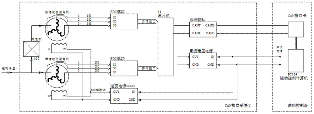
[0061] The system consists of a reducer, two self-aligning machines for coarse and fine channels, and a circuit board for the receiver. The circuit schematic diagram is as follows Figure 7 shown.

[0062] The receiver circuit board consists of: DC to 400Hz115V excitation power supply module, two SDC modules, single-chip microcomputer, CAN driver module, and DC power supply module. Its principle block diagram is as follows: figure 2 shown.

[0063] Its single-chip microcomputer software includes: read the angle digital quantum program of the SDC module, carry out angle digital coarse channel and fine channel angle combination operation subroutine, angle full angle zero position correction operation subroutine, fine channel zero position data correction value receiving, saving and reading Subroutines, subroutines for ...

Embodiment 2

[0066] Embodiment 2 Technical solution: CAN interface receiver using resolver solution

[0067] The system consists of a reducer, two rotary transformers for coarse and fine channels, and a receiver circuit board, such as Figure 8 shown.

[0068] The composition of the receiver circuit board includes: DC to 400Hz115V excitation power module, SDC module, single-chip microcomputer, CAN driver module, DC power module, other schematic diagrams such as Figure 8 shown.

[0069] Its single-chip microcomputer software includes: read the angle digital quantum program of the SDC module, carry out angle digital coarse channel and fine channel angle combination operation subroutine, angle full angle zero position correction operation subroutine, fine channel zero position data correction value receiving, saving and reading Subroutines, subroutines for communicating with the accompanying computer through the CAN interface, subroutines for analyzing and executing commands from the accom...


PUM


Abstract

The invention provides a digital trusted instrument with a CAN interface. An external mechanical rotation angle variation quantity is transferred to a second automatic angle adjusting machine, and a fine channel angle digital quantity is obtained through an SDC module. The external mechanical rotation angle variation quantity is transferred to a first automatic angle adjusting machine through a speed reducer, and a coarse channel angle digital quantity is obtained through an SDC module. The coarse channel angle digital quantity and the fine channel angle digital quantity are subjected to coarse and fine combined operation of a single chip microcomputer, and a 17-bit trusted instrument position digital quantity is obtained. The trusted instrument position digital quantity is transmitted to a servo controller by a CAN bus driver module through a CAN data bus. A power supply module supplies power to the SDC modules, the single chip microcomputer and the CAN bus driver module. According to the digital trusted instrument, the direct influence on precision by excitation power supply interference is small, the conversion precision is ensured, and the calculation workload of a servo control computer is reduced.

Description

technical field [0001] The invention belongs to an angle sensor product and relates to a servo system. Background technique [0002] The angle position sensor commonly used in the follow-up system is the receiver. The working principle of the traditional receiver is to transmit the external rotation angle change signal to the receiver through the mechanical transmission, and transmit the mechanical angle change (or the speed conversion through the reducer) to the self-aligning machine (or the rotation angle) inside the receiver. Transformer), converted into 3-phase (same phase and different amplitude) AC analog signal output, and transmitted to the servo controller through the signal transmission cable, and the servo controller converts the 3-phase AC analog signal into an angle digital signal through SDC conversion . Because the accuracy of a single auto-alignment machine (or resolver) is not enough, two resolvers are required to measure with different speeds, and then th...

Claims


Application Information

Patent Timeline
Patent Type & Authority Applications(China)
IPC IPC(8): G01D5/12
Inventor 王世凯代普王德强王兴梅孔祥宣
Owner 中国兵器工业第二〇二研究所
Why Eureka
Try Eureka