Improved 2.4GHz LTCC power divider

A power divider and improved technology, applied in the microwave field, can solve the problems of difficulty in mass production, large number of components, unfavorable miniaturization, etc., and achieve the effects of good phase consistency, high output isolation and compact structure

Inactive Publication Date: 2015-02-04
NO 55 INST CHINA ELECTRONIC SCI & TECHNOLOGYGROUP CO LTD
View PDF3 Cites 23 Cited by
  • Summary
  • Abstract
  • Description
  • Claims
  • Application Information

AI Technical Summary

Problems solved by technology

[0004] Surface-mounted power dividers generally use lumped parameter circuits to achieve one-time co-firing of inductors and capacitors in a three-dimensional manner. However, power divider circuits construc...

Method used


Image

  • Improved 2.4GHz LTCC power divider
  • Improved 2.4GHz LTCC power divider
  • Improved 2.4GHz LTCC power divider

Examples


Embodiment Construction

[0015] Below in conjunction with accompanying drawing and specific embodiment, further illustrate the present invention, should be understood that these embodiments are only for illustrating the present invention and are not intended to limit the scope of the present invention, after having read the present invention, those skilled in the art will understand various aspects of the present invention Modifications in equivalent forms all fall within the scope defined by the appended claims of this application.

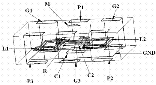
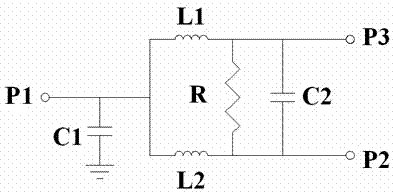
[0016] Such as figure 1 As shown, the structure of the improved 2.4GHz LTCC power divider includes: an input port P1, the first output port P2, the second output port P3, the first external side print G1, the second external side print Ground G2, third external printed ground G3, internal ground GND, ground capacitor C1, output parallel capacitor C2, first inductor L1, second inductor L2, isolation resistor R, and printed mark M.

[0017] Both the first inductance L1 an...


PUM


Abstract

The invention provides an improved 2.4GHz LTCC power divider of which the structure comprises an input port P1, a first output port P2, a second output port P3, a first external side printing ground G1, a second external side printing ground G2, a third external side printing ground G3, an internal ground GND, a ground capacitor C1, an output parallel-connected capacitor C2, a first electric inductor L1, a second electric inductor L2, an isolation resistor R and a printing mark M. Working frequency range is 2.3GHz-2.5GHz, which covers all frequency range of 2.4GHz application. The circuit mode adopted by a common lumped parameter power divider is improved with respect to the structure so that the number of elements is effectively reduced, element value is reduced, and thus the power divider is enabled to be more suitable for batch production of miniaturized devices. The improved 2.4GHz LTCC power divider has substantial advantages of being compact in structure, small in size, high in output isolation, low in insertion loss, great in phase consistency and high in amplitude balance degree.

Description

technical field [0001] The present invention relates to an improved LTCC power divider which covers the 2.4GHz application frequency band and has the advantages of small size, high output isolation, small insertion loss, good phase consistency, high amplitude balance, and suitable for miniaturized batch production. The utility model belongs to the field of microwave technology. Background technique [0002] In recent years, due to the rise of portable communication products and the demand for high-density IC packaging, LTCC technology has more application space. Through LTCC technology, passive components such as capacitors, inductors, and transmission lines can be completely buried in the medium and completed in the form of multi-layer circuits. They can make full use of the three-dimensional space and open up new directions for the development of miniaturized three-dimensional microwave passive devices. . [0003] Power splitters are widely used in RF / microwave transceiv...

Claims


Application Information

Patent Timeline
IPC IPC(8): H01P5/16H03H7/38
Inventor 郑琨
Owner NO 55 INST CHINA ELECTRONIC SCI & TECHNOLOGYGROUP CO LTD
Why Eureka
Try Eureka