Eureka AIR delivers breakthrough ideas for toughest innovation challenges, trusted by R&D personnel around the world.

Iteration de-mapping decoding device

A decoding device and iterative solution technology, applied in the directions of code conversion, coding, coding components, etc., can solve problems such as large hardware overhead, and achieve the effect of small hardware overhead and simple implementation.

Active Publication Date: 2015-02-04
ALICORP
View PDF5 Cites 8 Cited by
  • Summary
  • Abstract
  • Description
  • Claims
  • Application Information

AI Technical Summary

Problems solved by technology

However, this method requires a huge storage space to store the lookup table, so there is also the problem of large hardware overhead.

Method used


Image

  • Iteration de-mapping decoding device
  • Iteration de-mapping decoding device
  • Iteration de-mapping decoding device

Examples


Embodiment Construction

[0047] Various exemplary embodiments will be described more fully hereinafter with reference to the accompanying drawings, in which some exemplary embodiments are shown. However, inventive concepts may be embodied in many different forms and should not be construed as limited to the illustrative embodiments set forth herein. Rather, these exemplary embodiments are provided so that this disclosure will be thorough and complete, and will fully convey the scope of the inventive concept to those skilled in the art. In the drawings, the size and relative sizes of layers and regions may be exaggerated for clarity. Like numbers indicate like components throughout.

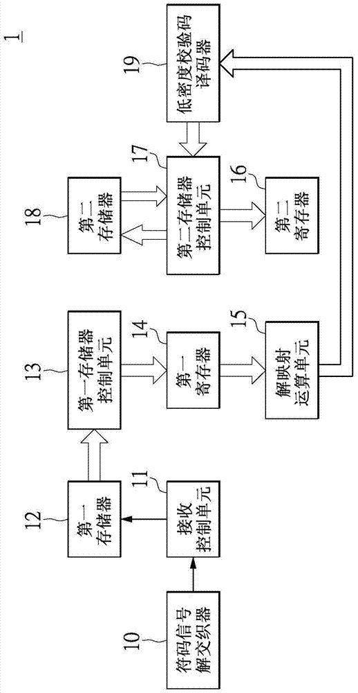
[0048] First, please refer to figure 1 , figure 1is a block diagram of an iterative demapping and decoding device according to an embodiment of the present invention. The iterative demapping and decoding device 1 can be used in a receiver in a communication system, especially a receiver of a digital television broadca...


PUM


Abstract

Provided is an iteration de-mapping decoding device. A storage device control unit is applied to store M first feedback logarithmic likelihood ratio generated by a low-density check code decoder each time to a storage device in a parallel way, and the M*(N-1) first feedback logarithmic likelihood ratio stored in the storage device is extracted from the storage device to be temporarily stored to a register. A de-mapping operation unit is used for extracting the temporarily stored M*(N-1) first feedback logarithmic likelihood ratio from the register, and calculating M specific bits of each logarithmic likelihood ratio according to the extracted M*(N-1) first feedback logarithmic likelihood ratio.

Description

technical field [0001] The present invention relates to a communication system, in particular to an iterative demapping and decoding device applicable to a second-generation digital television broadcasting (Digital Video Broadcasting—Second Generation Terrestrial, DVB-T2) system. Background technique [0002] The decoding device of the communication system can use an iterative method to calculate the log likelihood ratio (log likelihood ratio) of each bit of the code signal, so as to accurately know the bits of the code signal received by the decoding device value. For example, the second-generation digital TV terrestrial broadcasting standard discloses a calculation method, the formula of which is as follows: [0003] LLR ( b i ) = min x ...

Claims


Application Information

Patent Timeline
IPC IPC(8): H04L1/00H04N21/2383
CPCH04L1/0052H03M13/1165H03M13/255H03M13/271H03M13/6325H04L1/005H04L1/0071H04L2001/0093
Inventor 李琳
Owner ALICORP
Why Eureka
Eureka Blog
Learn More