Method and device for distributing power

An allocation method and a technology for allocating equipment, applied in the field of communication, can solve problems such as unreasonable resource allocation

Inactive Publication Date: 2015-02-04
CHINA UNITED NETWORK COMM GRP CO LTD
View PDF5 Cites 5 Cited by
  • Summary
  • Abstract
  • Description
  • Claims
  • Application Information

AI Technical Summary

Problems solved by technology

[0004] Embodiments of the present invention provide a power allocation method and device, which ca

Method used


Image

  • Method and device for distributing power
  • Method and device for distributing power
  • Method and device for distributing power

Examples


Embodiment 1

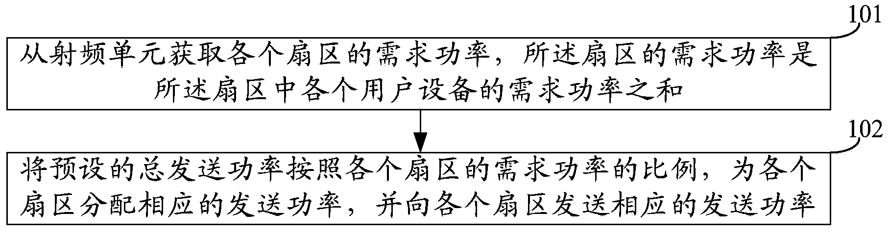
[0025] An embodiment of the present invention provides a power allocation method, such as figure 2 shown, including:

[0026] Step 101. Obtain the required power of each sector from the radio frequency unit, where the required power of the sector is the sum of the required power of each user equipment in the sector.

[0027] The radio frequency unit may obtain the required power of each user equipment in each sector, calculate the sum of the required power of each user equipment in the sector, and obtain the required power of the sector.

[0028] Among them, in some cases, in order to ensure the communication quality, the required power of the user equipment will be adjusted accordingly. Correct demodulation, that is, the transmission power of the base station must be large enough to overcome the attenuation of the signal through long-distance transmission; the user equipment is blocked by buildings or other, and in the wireless shadow area, the required power must also be l...

Embodiment 2

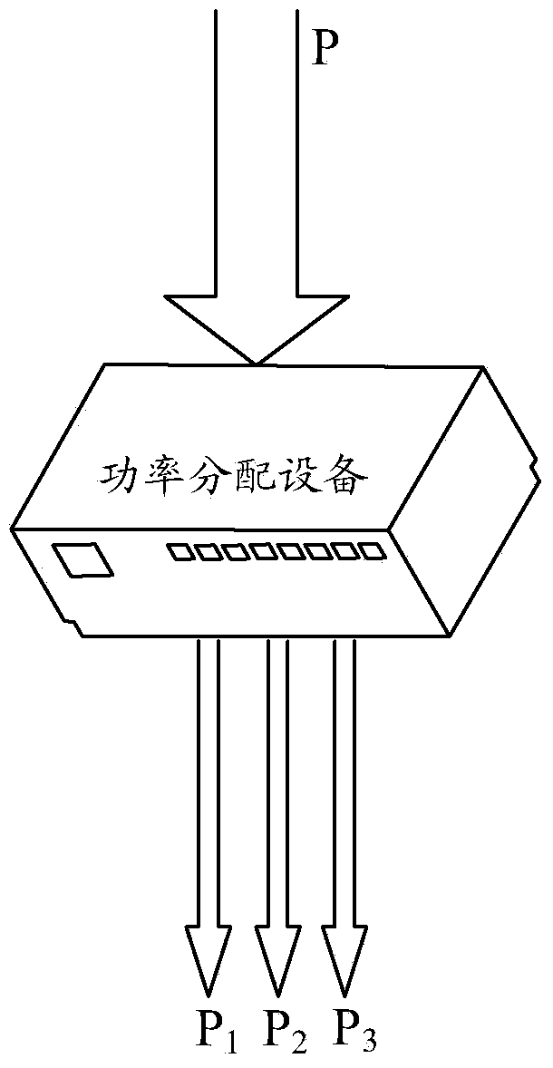
[0035] An embodiment of the present invention provides a power allocation method, which is applied to a power divider in a base station. The power divider can allocate transmission power for a wireless signal so that the wireless signal can be sent to a user equipment in a corresponding sector. The embodiment of the present invention The user equipment in is all equipment for business communication, such as Figure 4 shown, including:

[0036] Step 201, turn on each device in the base station.

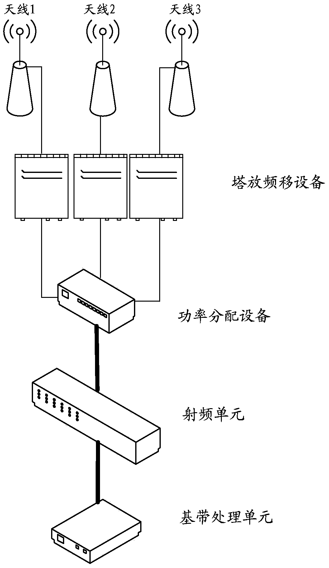
[0037] In this embodiment, the antenna (receiving antenna and transmitting antenna), power distribution equipment, frequency shift tower equipment, radio frequency unit and baseband processing unit are turned on to ensure that wireless signals can be sent and received normally.

[0038] Step 202, when initially starting up, equally distribute transmit power for each sector.

[0039]Each sector corresponds to an antenna port. The number of sectors can be determined according to the nu...

Embodiment 3

[0056] An embodiment of the present invention provides a power distribution device 30, such as Figure 5 As shown, can include:

[0057] The obtaining power unit 301 is configured to obtain the required power of each sector from the radio frequency unit, where the required power of the sector is the sum of the required power of each user equipment in the sector.

[0058] A power allocation unit 302, configured to allocate the preset total transmission power to each sector in proportion to the required power of each sector, and send the corresponding transmission power to each sector .

[0059] Compared with the prior art, the device provided by the embodiment of the present invention can allocate the total transmission power to each sector according to the obtained ratio of the required power of each sector, therefore, the required power of each sector can be Changes in the corresponding ratio, thereby changing the transmission power allocated by each sector, so that each se...


PUM


Abstract

The invention provides a method and a device for distributing power, relating to the field of communication and being capable of solving the problem of unreasonable resource distribution caused by power distribution at a fixed proportion. The method for distributing the power comprises the steps of: obtaining required power of each section from a RF (Radio Frequency) unit, wherein the required power of each section is the sum of the required power of each user equipment in the section; distributing corresponding sending power of the preset total sending power for each section according to the proportion of the required power of each section, and distributing corresponding sending power for each section. The provided method and device for distributing the power are used for antenna resource distribution.

Description

technical field [0001] The present invention relates to the communication field, in particular to a power allocation method and equipment. Background technique [0002] With the popularization of wireless devices, especially mobile phones, wireless communication systems are more and more widely used in real life. The wireless communication system is a system realized by the propagation of electromagnetic waves in free space, which may include antennas (receiving antennas and transmitting antennas), power distribution equipment, frequency shift tower equipment, radio frequency units and baseband processing units, such as figure 1 shown. [0003] In the prior art, the transmission process of the wireless signal needs to go through the following steps. After the wireless signal is processed by the baseband processing unit and the radio frequency unit, the existing power distribution equipment allocates the total transmission power in a fixed ratio according to the correspondin...

Claims


Application Information

Patent Timeline
IPC IPC(8): H04W52/34
CPCH04W52/346
Inventor 韩玉楠李轶群
Owner CHINA UNITED NETWORK COMM GRP CO LTD
Why Eureka
Try Eureka