
Rotary type bi-directional buffer device of aircraft docking mechanism

A technology of docking mechanism and two-way buffering, which is applied to the docking device of aerospace vehicle, low internal friction spring, etc., can solve the problem that the two-way transmission buffer device cannot adapt to the occasion of large-angle buffering stroke, etc., and achieves simple structure and smooth torque-angle characteristic curve. , the effect of high reliability

Inactive Publication Date: 2012-10-03
SHANGHAI AEROSPACE SYST ENG INST
View PDF0 Cites 7 Cited by
  • Summary
  • Abstract
  • Description
  • Claims
  • Application Information

AI Technical Summary

Problems solved by technology

[0005] In order to solve the problem that the existing two-way transmission buffer device cannot adapt to the occasion of large-angle buffer stroke, the purpose of the present invention is to provide a rotating two-way buffer device for aircraft docking mechanism

Method used


Image

  • Rotary type bi-directional buffer device of aircraft docking mechanism
  • Rotary type bi-directional buffer device of aircraft docking mechanism
  • Rotary type bi-directional buffer device of aircraft docking mechanism

Examples


Embodiment 1

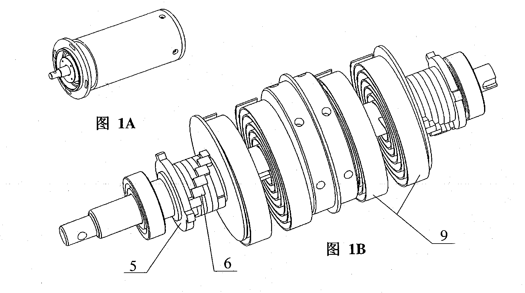
[0030] Figure 1~4 It is an embodiment of the single-rotation rotary two-way buffer device of the aircraft docking mechanism of the present invention. This mechanism can realize the collision buffer between the XX aircraft and the YY aircraft, reduce the peak load during the collision and impact, and realize the recovery correction.

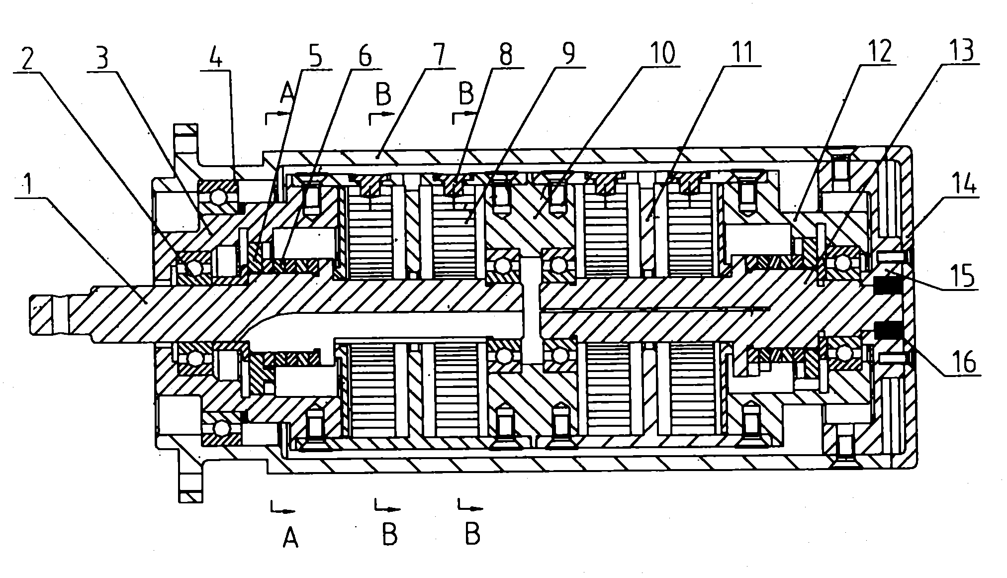
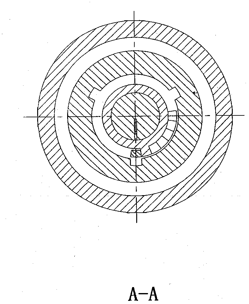
[0031] figure 1 A is the outline drawing of the single-shaft rotary two-way buffer device; figure 1 B is the exploded view of the device after removing the shell; figure 2 Is a sectional view; image 3 Is along figure 2 A cross-sectional view taken on line A-A in; Figure 4 Is along figure 2 Sectional view taken on line B-B in.

[0032] Such as Figure 1~4 As shown in the embodiment, the device includes: rotating shaft 1, A bearing 2, front sleeve 3, B bearing 4, cam disk I5, cam disk II6, immovable housing 7, bayonet 8, planar scroll spring 9, The coupling body 10, the movable housing 11, the rear sleeve 12, the shaft 13, the housing 14, the baffl...

Embodiment 2

[0039] Figure 5-9 It is an embodiment of the dual-rotation-axis rotating bidirectional buffer device of the aircraft docking mechanism of the present invention. The device can realize differential buffering between the two shafts in the XX aircraft docking buffer mechanism.

[0040] Figure 5 A shows the internal structure of Example 2; Figure 5 B shows its appearance. Image 6 Is a sectional view; Figure 7 Is along Image 6 A cross-sectional view taken on line A-A in; Figure 8 Is along Image 6 Sectional view taken on line B-B in; Picture 9 Is along Image 6 A cross-sectional view taken along the line C-C.

[0041] Such as Figure 5-9 As shown in the embodiment, the device includes: a rotating shaft 21, a C bearing 22, a cam sleeve 23, a housing 24, a spacer 25, a bayonet 26, a planar scroll spring 27, and a cam disc 28.

[0042] Such as Figure 5 As shown in A, the flat scroll spring 27 is divided into left and right parts, and they are installed in the same direction. The t...


PUM


Abstract

The invention discloses a single-shaft rotary two-way buffer device for an aircraft docking mechanism; it includes: a cylindrical body composed of a fixed shell, a shell, and a baffle, in which a rotating shaft and a shaft connected to the aircraft collision body are installed; Plane scroll springs are respectively installed on the and shafts. Each set of springs has two sections, separated by a movable housing; the inner end of the scroll spring is fixed on the rotating shaft or shaft, and the outer edge end is fixed on the movable housing. ; Cam disc groups are respectively installed in the front sleeve and rear sleeve of the rotating shaft or shaft; there is a bump on the rotating shaft or shaft and the cam disc respectively; when the movable housing is rotated and the pre-tightening torque of the spring reaches the specified value, the The bumps fit together and are tightened with screws to preload the spring. The invention also discloses a double-shaft rotating two-way buffer device. The invention solves the problem of the large-angle buffer stroke of the aircraft docking mechanism, and achieves the beneficial effects of simple structure and high reliability.

Description

Technical field [0001] The invention relates to space vehicle equipment in the aerospace field, and in particular to a rotating two-way buffer device in a space vehicle docking mechanism. Background technique [0002] Relevant technologies for realizing the rotational buffering function include seat belts on automobiles, which use the multi-rotation nature of the scroll spring to achieve a large-stroke buffering effect. The disadvantage is that it can only realize buffering in one direction, and there is no specific mechanism to complete multiple functions. Turn number rotary output. [0003] Currently, in the field of spacecraft docking mechanisms, there is a device that can realize a two-way transmission and buffering function. This device uses a spiral torsion spring to achieve rotational buffering in two directions. Its shortcoming is that its buffering function relies on a torsion spring. It is realized by tightening and releasing, so the rotation capacity is less than...

Claims


Application Information

Patent Timeline
IPC IPC(8): B64G1/64F16F3/04
Inventor 杨新海肖杰刘仲
Owner SHANGHAI AEROSPACE SYST ENG INST
Features
  • Generate Ideas
  • Intellectual Property
  • Life Sciences
  • Materials
  • Tech Scout
  • Unparalleled Data Quality
  • Higher Quality Content
  • 60% Fewer Hallucinations
Learn More