Sealing element for a hydraulically-actuated friction clutch

A technology for friction clutches and sealing elements, which is applied to clutches, engine seals, fluid-driven clutches, etc., can solve the problems of troublesome and expensive manufacturing, complex structure of friction clutches, etc., and achieve the effect of simple manufacturing

Active Publication Date: 2015-02-11
SCHAEFFLER TECH AG & CO KG
View PDF16 Cites 8 Cited by
  • Summary
  • Abstract
  • Description
  • Claims
  • Application Information

AI Technical Summary

Problems solved by technology

Therefore, the structure of such a friction clutch is very complicated
The production of such friction clutches therefore also involves a plurality of individual steps, which makes production complex and expensive

Method used


Image

  • Sealing element for a hydraulically-actuated friction clutch
  • Sealing element for a hydraulically-actuated friction clutch

Examples


Embodiment Construction

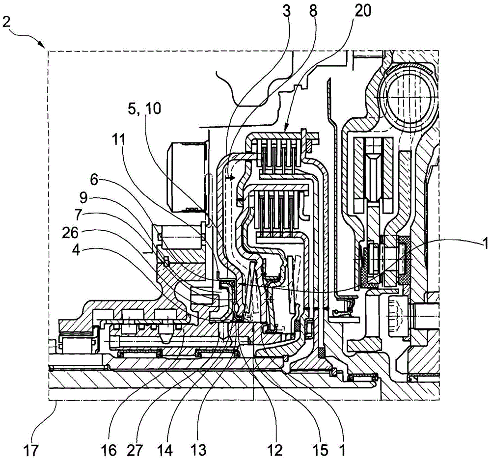
[0036] figure 1 A detail of a friction clutch 2 is shown, in which a separate sealing element 1 is arranged separately next to an actuating piston 3 , which is provided in the axial direction of movement for pressing against a disk pack 20 . In this case, the sealing element 1 is pot-shaped and surrounds the pressure chamber 4 on both sides with its pot wall 10 and its displacement surface 7 , which is simultaneously formed as a sliding surface 5 . The rear wall 26 of the pressure chamber 4 is arranged rigidly on the rotor 16 and thus delimits the pressure chamber 4 . In order to ensure a minimum distance between the actuating piston 3 or the sealing element 1 and the rear wall 26 , the sealing element 1 has an axial stop 14 which is integrated into the displacement surface 7 . Arranged on the rear wall 26 is a first axial sealing means 6 which slides on the sliding surface 5 . In order to stabilize the sliding surface 5 or the tank wall 10 , a flange 11 is provided which is...


PUM


Abstract

The invention relates to a sealing element for a hydraulically-actuated friction clutch, wherein the sealing element is separately positionable between an actuating piston of a friction clutch and a pressure chamber for actuating said actuating piston and has a first axially-oriented sliding surface for a first axial sealing means. With the seal member proposed here, it is possible to implement different functions with simple means in a complex friction clutch, in particular a double clutch with simple means and at low cost.

Description

technical field [0001] The invention relates to a sealing element for a hydraulically actuated friction clutch, in particular for a motor vehicle. Background technique [0002] Various hydraulically actuated friction clutches are known in the prior art. For this purpose, at least one piston which is movable (to and fro) by means of a pressure chamber is arranged in the friction clutch. In efficient friction clutches there is an increased number of components which have to fulfill different functions in the friction clutch. Therefore, the structure of such a friction clutch is very complicated. The production of such friction clutches therefore also involves a plurality of individual steps, which makes production complex and expensive. Contents of the invention [0003] Proceeding from this, the object of the invention is to at least partially overcome the disadvantages known from the prior art. This object is solved by the features of the independent claims. Advantage...

Claims


Application Information

Patent Timeline
Patent Type & Authority Applications(China)
IPC IPC(8): F16D25/12F16J15/32F16D25/0638
CPCF16D25/10F16D25/12F16D25/0638F16D2021/0661F16D2300/08
Inventor J·芬克
Owner SCHAEFFLER TECH AG & CO KG
Why Eureka
Try Eureka