
Elbow for various pipelines

A technology of pipe elbows and types, applied in the directions of elbows, pipes/pipe joints/fittings, pipes, etc., can solve the problems of difficult entry and exit, cable jamming, cumbersome construction process, etc., to reduce the bending arc and prevent clogging Effect

Inactive Publication Date: 2015-02-11
甘国强
View PDF7 Cites 0 Cited by
  • Summary
  • Abstract
  • Description
  • Claims
  • Application Information

AI Technical Summary

Problems solved by technology

[0003] In specific construction, for example, the cables need to be threaded in each section of the line pipe in turn. For the turning of the wiring, a 90° elbow joint is required to realize the connection between the two sections of straight pipes, and the cables are threaded through the 90° elbow. The joint is the most difficult to implement in construction; the existing 90° elbow joint is formed by two vertical straight-through pipes intersecting. During the threading process, the cables in the pipe are often stuck by the 90° bend in the pipe, making it difficult to enter and exit easily , especially when thick cables are threaded into small-diameter elbows, it is necessary to manually bend the cables to pass the cables section by section, which makes the construction process cumbersome and is an important reason for affecting the construction schedule.
[0004] There are also various types of pipe elbows that involve turning, such as pipe elbows that transport gas or liquid. In order to facilitate the production of molds, 90° elbows are often used. Because of their large bending arcs, there are different degrees of blocking obstacles, such as Sewers are often clogged with accumulated grease

Method used


Image

  • Elbow for various pipelines
  • Elbow for various pipelines
  • Elbow for various pipelines

Examples


Embodiment Construction

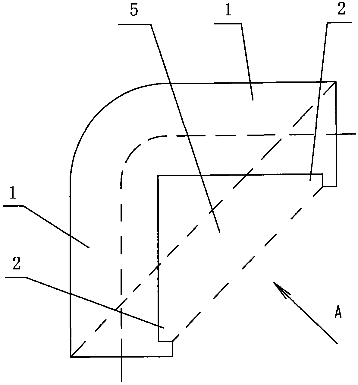
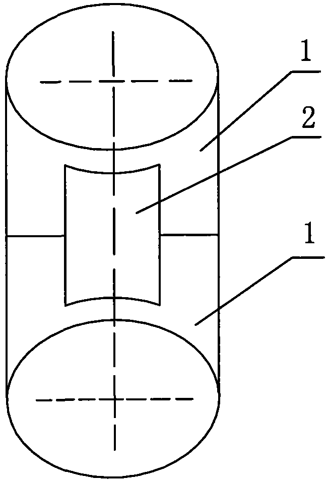
[0029] The technical solution of the present invention will be further described below in conjunction with the embodiments shown in the accompanying drawings:

[0030] A structure of the multi-purpose pipeline elbow of the present invention comprises two sections of straight pipe 1, the distance from the center of the nozzle of the two sections of straight pipe 1 to the vertical foot is equal, the two sections of straight pipe 1 vertically intersect (penetrate), and the outside of the straight pipe 1 is semicircle The outer corner of the circular arc transition at the point where the circumference intersects, the inner half circle of the straight pipe 1 intersects to form an inner angle of 90°, and the inner half circle of the two straight pipes 1 is respectively centered with an axial notch 2, and the inner ends of each notch 2 are connected. The outer end of the mouth 2 stops at the nozzle edge of the corresponding straight pipe 1, and each side end of each notch 2 does not e...


PUM


Abstract

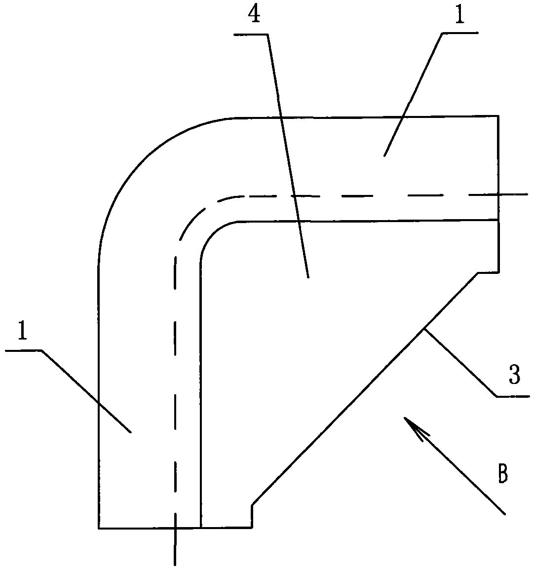
The invention discloses an elbow for various pipelines. The exterior angle of the through portion of semi-circumferences on the outer sides of two through straight tubes is in arc transition, the interior angle of the through portion of the inner sides of the two straight tubes is 90 degrees, an axial notch is formed in the center of each of the semi-circumferences of the inner sides of the two straight tubes, the inner ends of the two notches are communicated, the outer ends of the two notches are arranged at tube openings of the corresponding straight tubes, each end of each notch is not exposed out of the circumferential end of the inner side of the corresponding straight tube, and accordingly, an open or sealed straight channel between the tube openings of the two straight tubes is formed. The invention further discloses another elbow for various pipelines. The two straight tubes are communicated through a small-radian bent tube. The open or sealed straight channel is formed between the two straight tubes, so that the distance of the route that an object passes through the straight tubes is reduced, obstacles at the interior angle of the straight tubes are avoided, and the object can pass through the straight tubes conveniently. The bending radian of the elbow is lowered, liquid can pass more smoothly, and the pipelines are prevented from being blocked.

Description

(1) Technical field: [0001] The invention relates to site construction equipment, in particular to a variety of pipeline elbows. (two) background technology: [0002] I first applied to the National Patent Office for the name "Multiple Pipeline Elbows" (invention patent number: 201310347900.9), because the product and composition are not comprehensive and in the construction of electrical and automation system wiring projects in industrial and civil buildings, often The method of laying wire tubes is used to protect cables, facilitate cable maintenance, and keep the walls of buildings clean and beautiful. [0003] In specific construction, for example, the cables need to be threaded in each section of the line pipe in turn. For the turning of the wiring, a 90° elbow joint is required to realize the connection between the two sections of straight pipes, and the cables are threaded through the 90° elbow. The joint is the most difficult to implement in construction; the existi...

Claims


Application Information

Patent Timeline
Patent Type & Authority Applications(China)
IPC IPC(8): F16L43/00F16L41/02F16L41/03
CPCF16L43/00
Inventor 甘国强
Owner 甘国强
Learn More