Eye-tracking using a GPU

a gpu and eye tracking technology, applied in the field of eye tracking, can solve the problems of inflexibility to belong to the standard equipment of new laptops, inability to include eye tracking capabilities, and inability to solve problems such as inability to solve eye tracking problems, and achieve the effects of avoiding aliasing-related artefacts, facilitating geometric deformation measurements, and easy extraction

Active Publication Date: 2013-01-01
TOBII TECH AB
View PDF4 Cites 21 Cited by
  • Summary
  • Abstract
  • Description
  • Claims
  • Application Information

AI Technical Summary

Benefits of technology

[0015]Further, according to the invention, a signal encoding an image of the eye to be tracked is received at the graphics card. Because a number of preliminary processing steps can thus be performed by the graphics card, the amount of data reaching the CPU can be considerably decreased by filtering out irrelevant image segments, pre-processing the image data, extracting coordinates of image features and the like. Additionally, the fact that the image signal is received at the graphics card, where it is processed, shortens the path of the input data flow, which would otherwise be transmitted over the USB interface, the internal bus and the graphics port or over some other chain of connected motherboard devices. This efficient routing of the input data flow constitutes another advantage of the invention.
[0016]In a second aspect of the invention, there is provided a computer-program product for carrying out the above method. In a third and fourth aspect of the invention, there are provided a gaze tracking system and a personal computer system (this term is to be understood as indicated above) in which such gaze tracking system is integrated. The gaze tracking system comprises a visual display, a camera, a graphics card, and a gaze-point determining module. Here, the gaze-point determining module, which may be a software module having authority to allocate resources within the system, is operable to cause the system to function in accordance with the method set forth above. A fifth aspect of the invention relates to use of a graphics card for carrying out certain tasks in connection with gaze tracking of an eye watching a visual display.
[0017]In one embodiment of the present invention, the graphics card extracts one or more image features in the corneo-scleral reflection of the screen pattern. The graphics card then deduces the corresponding positions of the one or more image features in the screen pattern from the display signal, which is provided to the visual display by the graphics card itself. The coordinates of the image features before and after reflection in the cornea are used to determine a position of the eye. As an alternative, the display signal can be taken as starting point and regions of the screen pattern—with deformation, mirroring etc. taken into account—can be searched for in the reflection. In some embodiments, also the orientation of the eye is deduced from these coordinates.
[0018]In another embodiment, the eye is illuminated by at least one reference illuminator adapted to emit invisible light for producing a glint, a small, distinct luminous reflection on the corneo-scleral surface of the eye. The position of the glint, which is deduced from the image of the eye, is used for determining the gaze point of the eye. Wavelengths in the infrared (IR) and near-infrared (NIR) ranges are suitable for producing glints. Coaxial or non-coaxial illuminators, respectively for producing bright-pupil and dark-pupil eye images, may be applied, as considered appropriate. The reference illuminators may be integrated in the visual display or arranged thereon in a detachable fashion. Advantageously, the reference illuminators are light-emitting diodes (LEDs) provided in fittings having hooks, clips, suction cups or similar means for securing them to the visual display. As an alternative, the reference illuminators may be provided behind the display screen and aligned with suitable partial apertures provided therein, as described in EP 09 157106.
[0019]In a further embodiment, the image of the eye is received using an imaging device which is synchronised with the visual display. If the visual display responds to the display signal in real time, i.e., by plotting the image with zero or no time delay, then the display signal can be used as a trigger to the imaging device. As an alternative, a dedicated trigger signal can be provided to both devices. Synchronisation is beneficial to the image quality because aliasing-related artefacts can be avoided by sampling the display image at the same frequency as it is updated. Among such artefacts are time oscillations of the (average) image intensity and steady or moving patterns of light and dark horizontal stripes. In particular, synchronisation between the imaging device and the visual display can be used for interlacing a distinctive reference pattern with the regular screen pattern. Advantageously, the regular screen pattern to be perceived by the human viewer occupies the largest part of a cycle while the reference pattern is displayed in a short time slot, invisibly to a human eye. The reference pattern may contain image features that can be extracted easily or may be devised to facilitate measurements of the geometric deformation inflicted by the reflection. In particular, the reference pattern may include invisible light, such as NIR light, emitted by the visual display or by reference illuminators.
[0020]In an alternative embodiment, the imaging device is instead synchronised with at least one reference illuminator. Hence, as a first option, the illumination by the reference illuminator(s) can be provided in a well-defined time slot, thereby enabling energy-economical operation of the reference illuminator. As a second option, a high degree of contrast can be achieved by subtracting the respective eye images with and without illumination by the reference illuminator.

Problems solved by technology

While eye tracking systems are utilised in a growing range of applications, they are not yet flexible enough to belong to the standard equipment of new laptops and desktops although web cameras do.
However, the computational complexity of eye tracking may be enough to dissuade a computer vendor from including such capabilities, as some eye tracking implementations occupy a large part of the input / output capacity, memory resources and data processing capacity of the central processing unit (CPU) when run on a personal computer in real time.
Such occupancy is detrimental to other functions of the computer; notably it may slow down execution of other processes and increase their latency.

Method used


Image

  • Eye-tracking using a GPU
  • Eye-tracking using a GPU
  • Eye-tracking using a GPU

Examples


Embodiment Construction

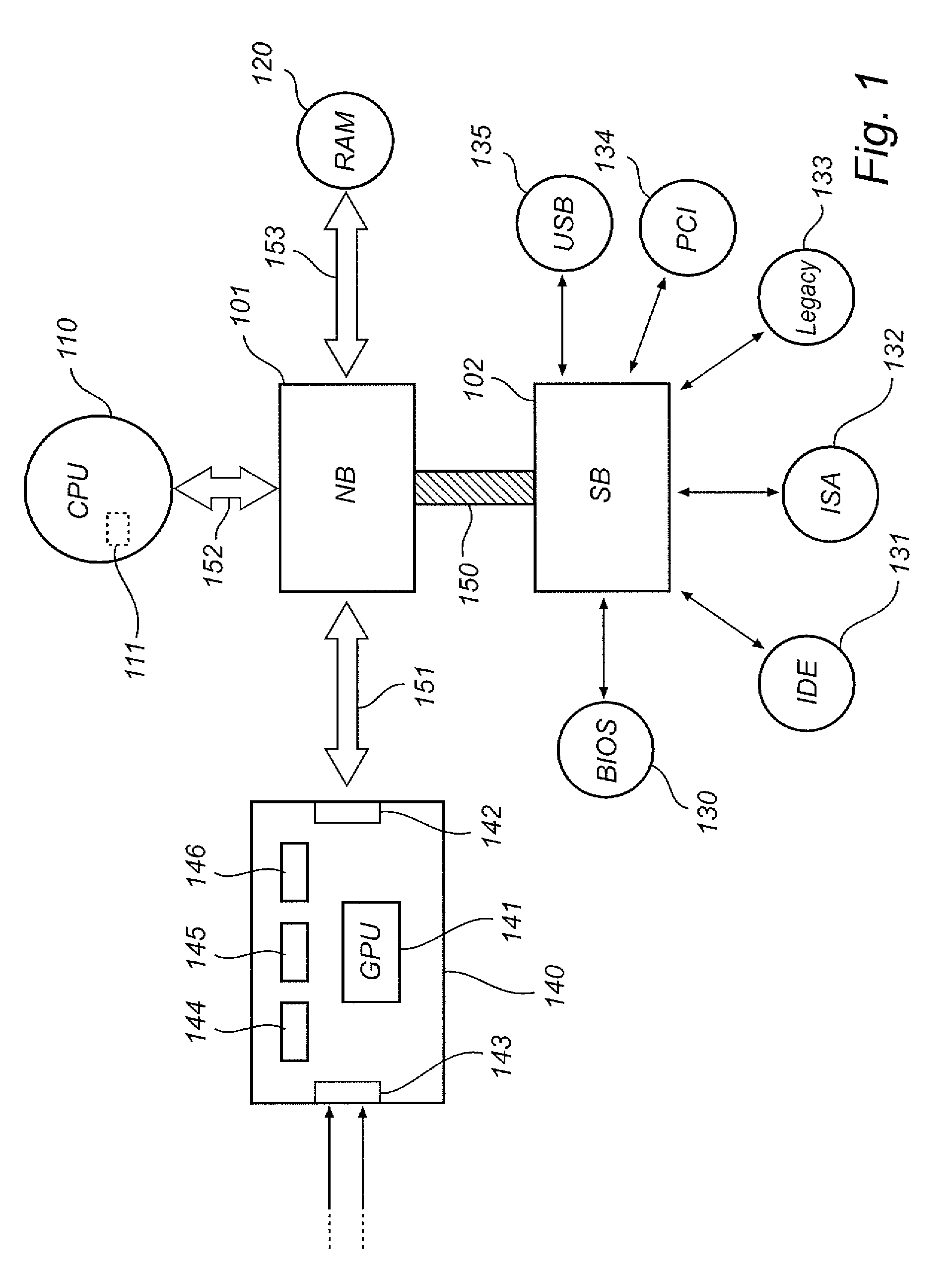
[0027]The structure of a motherboard in a typical personal computer will now be described with reference to FIG. 1. The chipset, or core logic, of the computer consists of the northbridge 101, or (integrated) memory controller, and the southbridge 102, or input / output controller hub. The northbridge 101 and southbridge 102 are communicatively connected by the internal bus 150. The southbridge 102 is generally used as an interface for devices with lower data rates than the northbridge 101. Thus, in this example, the southbridge 102 is connected to a basic input / output system (BIOS) 130, Integrated Drive Electronics (IDE) bus 131, an Industry Standard Architecture (ISA) bus 132, another legacy interface 133 to provide backward compatibility, a Peripheral Component Interconnect (PCI) bus 134 and a USB interface 135. The northbridge 101, which generally handles high-speed devices, is connected to a CPU 110 via a front-side bus 152 and to a random access memory unit 120 via a memory bus ...


PUM


Abstract

Provided is a method of determining a gaze point of an eye watching a visual display controllable by a display signal. The method comprises generating a display signal using a graphics card in order for the visual display to produce a screen pattern; receiving a signal encoding an image of the eye including a corneo-scleral reflection of the screen pattern; and determining, based on in part the geometry of said reflection, a gaze point of the eye, wherein said determining a gaze point includes utilizing the graphics card as a parallel processor.The image of the eye may be received directly at the graphics card. The graphics card may extract image features in the eye images. Reference illuminators may be used, and the screen pattern may be interlaced with a distinctive reference pattern.Further provided are a gaze-tracking system and a personal computer system adapted to determine a gaze point of a viewer.

Description

TECHNICAL FIELD[0001]The invention disclosed herein generally relates to eye tracking (determination of gaze point or gaze angle) using a computer system. In particular, the invention provides an efficient implementation of data input, data output and data processing for determining the gaze point of an eye watching a visual display forming part of a portable or stationary personal computer system, or a communication device with imaging and computing capabilities, such as a mobile telephone.BACKGROUND[0002]Monitoring or tracking eye movements and detecting a person's gaze point can be used in many different contexts. Eye tracking data can be an important information source in analysing the behaviour or consciousness of the person. It can be used both for evaluating the object at which the person is looking and for evaluating the respective person. The diverse uses of gaze point detection include studies on the usability of software and different types of interfaces; evaluation of we...

Claims


Application Information

Patent Timeline
Patent Type & Authority Patents(United States)
IPC IPC(8): A61B3/14A61B3/00G06F3/0346
CPCA61B3/113G02B27/0093G03B15/16G06K9/00604G06V40/19G06T1/00G06T7/60
Inventor BLIXT, PETERKOBETSKI, MIROSLAVHOGLUND, ANDERS
Owner TOBII TECH AB
Why Eureka
Try Eureka