Concrete processing device and method of building outline forming machine

A technology for building outlines and processing equipment, applied in ceramic molding machines, clay preparation devices, chemical instruments and methods, etc., can solve the problems of concrete segregation and "segregation, production efficiency decline, construction cost increase, etc., to shorten the path and time. , avoid pipe bending and improve production efficiency

Active Publication Date: 2016-05-25
BUILDERA CONSTR TECH SHANGHAI CO LTD
View PDF7 Cites 19 Cited by
  • Summary
  • Abstract
  • Description
  • Claims
  • Application Information

AI Technical Summary

Problems solved by technology

Obviously, this method is suitable for the molding of existing concrete structures, but cannot meet the concrete treatment requirements for building contour molding machines, such as: the fluidity of existing concrete is very good, so as to be able to adapt to the delivery of existing conveying systems , but the slump caused by this is very large (usually the slump of commercial pumped concrete is about 200), and the tolerance range of slump cannot be controlled very strictly, but because of the use of molds, the slump Therefore, the problem of slump can be remedied; for the concrete used in building contour forming machines, not only the slump is required to be relatively small, but also the slump tolerance range is very strict, otherwise the molding quality of the concrete structure cannot be guaranteed.
Practice has proved that in order to meet the molding quality requirements of the building contour molding machine, the concrete slump must be greatly reduced (such as reduced to below 80), and the existing conveying equipment (such as the commonly used pump) cannot work normally.
In short, the workability requirements of concrete used in building contour forming machines are very high, and the existing concrete treatment cannot meet the workability requirements, because there are many factors that affect the workability, such as water consumption, water-cement ratio, sand rate and including Cement types, aggregate conditions, time and temperature, admixtures, etc., so it is relatively difficult to control workability, and special concrete treatment methods must be used
[0004] Using the existing conveying system (commonly used pumps) to convey concrete, there are still problems such as pipe blockage, and at the same time, it will also lead to the problem of poor concrete quality
For example: due to the large pressure gradient change in the conveying pipeline, it is easy for water to penetrate from the aggregate gap at places with a large pressure gradient (such as pipeline bends, variable diameters, and hose arrangements in the middle of the pipeline), and make the aggregate Agglomeration of aggregates will cause pipe blockage; because the conveying pipeline is long and laid out in different horizontal and vertical directions, and the particle size and weight of aggregates vary greatly, it is easy for concrete to appear in the conveying pipeline. The phenomenon of segregation and "segregation" not only causes the separation of mortar and aggregate to block the pipe, but also leads to the deterioration of concrete quality; due to the long conveying process of concrete, it is inevitable that there will be temperature changes and uneven water-cement ratio during the conveying process. problems, resulting in poor workability of concrete, and unstable slump of concrete extruded from the nozzle, thus affecting the molding effect and quality of concrete structures
In order to solve the above-mentioned problems caused by the concrete conveying process, measures such as strict and precise control of water volume, water-cement ratio, sand rate, and cement types, aggregate conditions, time and temperature, and admixtures can be taken, but the effect is not great, but it will bring The problem of increased construction costs and decreased production efficiency

Method used


Image

  • Concrete processing device and method of building outline forming machine
  • Concrete processing device and method of building outline forming machine
  • Concrete processing device and method of building outline forming machine

Examples


Embodiment Construction

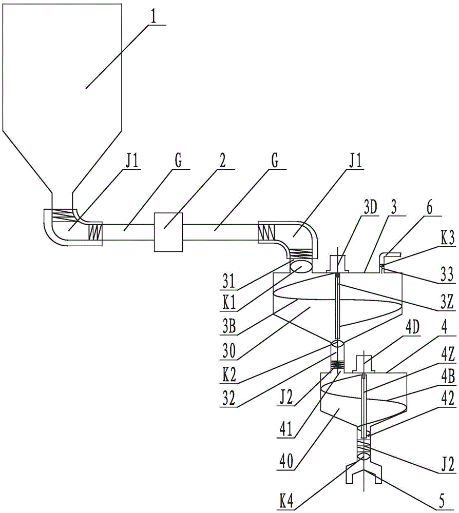
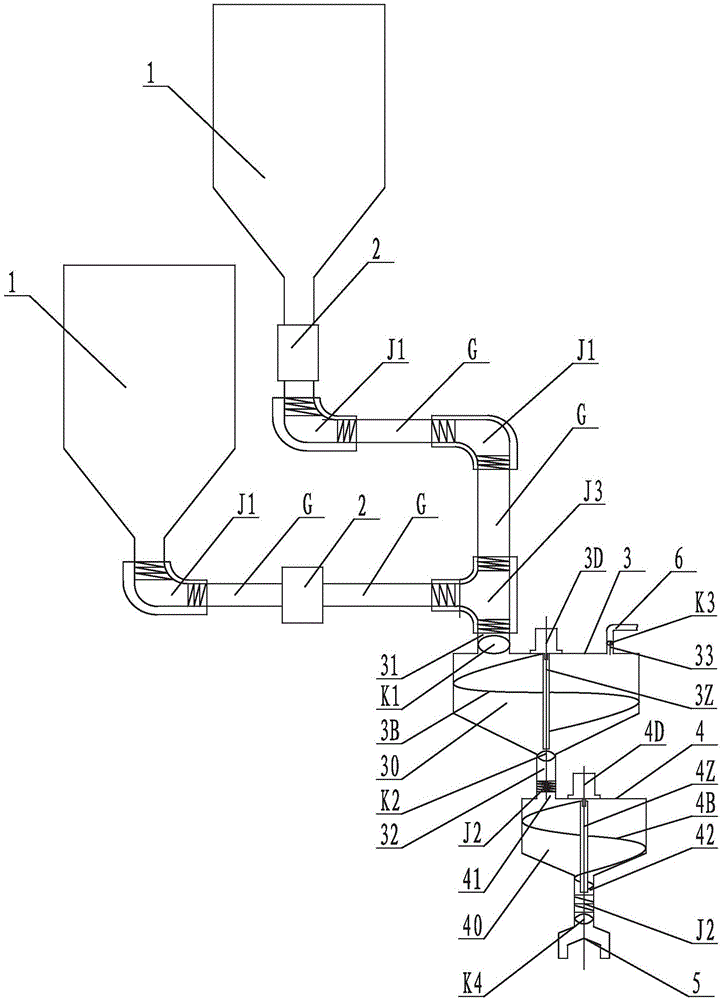
[0030] The following is attached Figures 1 to 3 The given examples further illustrate the specific implementation of the concrete processing equipment and processing method of the building contour forming machine of the present invention. The concrete processing equipment and processing method of the building contour forming machine of the present invention are not limited to the description of the following embodiments.

[0031] see figure 1 and figure 2, the concrete processing equipment of the architectural contour forming machine of the present invention includes: a raw material bin 1 for storing solid raw materials; a raw material pump 2 and a delivery pipe G for transporting the solid raw materials in the raw material bin 1 to the stirring integrated machine 3 In the mixing chamber 30; the mixing machine 3 is used to inject liquid raw materials, mix the solid raw materials with the liquid raw materials and then stir them into qualified concrete, and directly transpor...


PUM


Abstract

The invention discloses a concrete processing device and method of a building outline forming machine. The processing device comprises a raw material bin, a raw material pump, conveying pipes, a stirring and conveying integrating machine, an extruding device and a nozzle. The raw material bin is used for storing solid raw materials; the raw material pump and the conveying pipes are used for conveying the solid raw materials in the raw material bin into a stirring bin of the stirring and conveying integrating machine; the stirring and conveying integrating machine is used for injecting liquid raw materials, mixing and stirring the solid raw materials and the liquid raw materials to form qualified concrete, and directly conveying the concrete into the extruding machine; the extruding machine extrudes the concrete from the nozzle for printing. The processing method includes the steps of preparing of the raw materials, pipe and pump material conveying, water injecting mixing and stirring, material stirring and conveying and extruding printing. The path and the time required from generation to extruding printing of the concrete can be effectively shortened, the production efficiency and the forming effect of printing work can be improved, and the quality of the concrete structure can be improved.

Description

technical field [0001] The invention relates to the field of construction equipment, in particular to processing equipment and processing methods for mixing, conveying and extruding concrete used in building contour forming machines. Background technique [0002] As we all know, the existing building contours are usually formed by block stacking or concrete pouring, which has the disadvantages of long construction period, high construction cost, low degree of automation, large consumption of human and material resources, and poor environmental protection performance. U.S. Patent US7814937B2 discloses a machine with different characteristics that can be deployed. It is based on the principle of 3D printing and uses a 3D motion control system to control a nozzle for extruding concrete to move in 3D, so as to realize the rapid prototyping of the outline of the building. Such as floors, walls, roofs, etc. As a result, the equipment and technology commonly known as architectural...

Claims


Application Information

Patent Timeline
Patent Type & Authority Applications(China)
IPC IPC(8): B28B1/00B28B13/02B28C5/16B33Y30/00B33Y10/00
CPCB28B1/001B28B13/0235B28C5/16
Inventor B·克斯尼维斯张靖蒋旭峰宋立峰
Owner BUILDERA CONSTR TECH SHANGHAI CO LTD
Why Eureka
Try Eureka