Optical module

An optical module and optical transmission sub-module technology, applied in the field of optical communication, can solve the problems of discontinuous impedance between the laser driver chip and the flexible circuit board, affecting the quality of the transmitted optical signal signal, etc., so as to improve the continuity of the signal impedance and shorten the path. Effect

Active Publication Date: 2020-02-11
HISENSE BROADBAND MULTIMEDIA TECH
View PDF5 Cites 21 Cited by
  • Summary
  • Abstract
  • Description
  • Claims
  • Application Information

AI Technical Summary

Problems solved by technology

[0004] However, as the transmission rate of the optical module increases, the impedance matching requirements between its internal components are also increasing, and the above-mentioned laser driver chip is welded on the Driver pad, and the

Method used


Image

  • Optical module
  • Optical module
  • Optical module

Examples


Example Embodiment

[0029] The technical solutions in the embodiments of the present invention will be clearly and completely described below in conjunction with the accompanying drawings in the embodiments of the present invention. Obviously, the described embodiments are only a part of the embodiments of the present invention, rather than all the embodiments. Based on the embodiments of the present invention, all other embodiments obtained by those of ordinary skill in the art without creative work shall fall within the protection scope of the present invention.

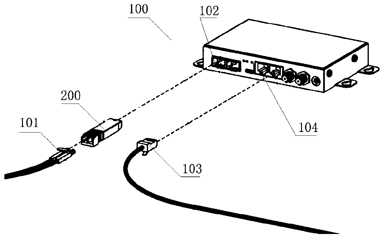
[0030] One of the core links of optical fiber communication is the mutual conversion of optical and electrical signals. Optical fiber communication uses information-carrying optical signals to be transmitted in optical fibers / optical waveguides and other information transmission equipment, and the passive transmission characteristics of light in optical fibers / optical waveguides can achieve low-cost and low-loss information transmission; ...


PUM


Abstract

The application provides an optical module, which comprises a circuit board. Laser driving chips on driving chip bonding pads, flexible board bonding pads, and differential signal wires for connectingthe flexible board bonding pads with the driving chip bonding pads are arranged on a top signal layer of the circuit board. Ground holes for differential signal returning are formed around each groupof flexible board bonding pads, driving chip bonding pads, and differential signal wires on the top signal layer, and a first grounding layer and a second grounding layer in the circuit board, so that a signal return path is reduced. Moreover, metal layers are laid in forward projection areas of the flexible board bonding pads and hollow areas are formed in the forward projection areas of the driving chip bonding pads; and metal layers are laid in the forward projection areas of the driving chip bonding pads on the second grounding layer so as to provide a signal backflow ground. On the basisof the design, the high-frequency performance coherence resistance can be improved and thus the impedance continuity between the laser driving chip and the flexible circuit board in working of the optical module is improved.

Description

technical field [0001] The present application relates to the technical field of optical communication, and in particular to an optical module. Background technique [0002] The optical module is mainly used for photoelectric and electro-optical conversion. Its transmitting end converts electrical signals into optical signals and transmits them through optical fibers, and its receiving end converts received optical signals into electrical signals. [0003] In order to realize the above-mentioned photoelectric conversion function, a standard optical module usually includes components such as a circuit board, a light emitting sub-module and a light receiving sub-module connected to the circuit board. Among them, when the optical module has airtightness requirements in the actual use process, the light emitting sub-module will adopt an airtight box packaging structure, and the airtight box is packaged with optical devices such as lasers, and then the airtight box The airtight ...

Claims


Application Information

Patent Timeline
IPC IPC(8): G02B6/42
CPCG02B6/4281
Inventor 孙金星
Owner HISENSE BROADBAND MULTIMEDIA TECH
Why Eureka
Try Eureka