Double-system heat pump defrosting method and device

A dual-system, heat pump technology, applied in lighting and heating equipment, damage protection, refrigeration components, etc., can solve the problems of insufficient heat absorption, reduced system safety, protective shutdown of the heat pump host, etc., to achieve low cost and structure Simple and safe system operation

Inactive Publication Date: 2015-02-11
LUOYANG ZHONGMAO ENVIRONMENTAL PROTECTION EQUIP
View PDF4 Cites 12 Cited by
  • Summary
  • Abstract
  • Description
  • Claims
  • Application Information

AI Technical Summary

Problems solved by technology

In this defrosting method, since the heat released by the refrigerant on the high-pressure side still comes from the heat absorbed by the evaporator, when the ambient temperature is low and the defrosting speed is not fast enough, there will not be enough heat absorbed, which will cause the heat pump host to have a protective shutdown
If a simple bypass is used, all the high-temperature gas discharged from the compressor is bypassed to the finned evaporator for rapid defrosting. After the gas refrigerant releases heat, part of it is converted into a high-pressure liquid. At the moment when the defrosting mode is switched to the heating mode, This part of high-pressure liquid can easily enter the compressor through the system pipeline, causing the compressor to appear liquid compression, which reduces the safety of the system. To solve this hidden danger, a refrigerant heating device can be installed between the finned evaporator and the compressor. This device only operates in the defrosting mode, which effectively prevents the liquid refrigerant from directly entering the compressor after defrosting, but the use of the refrigerant heating device increases the manufacturing cost and defrosting cost of the system

Method used


Image

  • Double-system heat pump defrosting method and device

Examples


Embodiment Construction

[0014] In conjunction with accompanying drawing, provide embodiment of the present invention as follows:

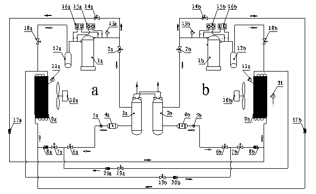
[0015] Such as figure 1 As shown: the dual-system heat pump defrosting device described in this embodiment includes two heating circuits and two sets of defrosting mechanisms. The composition and operation mode of the two heating circuits (a system heating circuit and b system heating circuit) are the same, including compressor 1a / 1b, auxiliary solenoid valve 2a / 2b, water-cooled condenser 3a / 3b, Dry filter 4a / 4b, sight glass 5a / 5b, heating solenoid valve 6a / 6b, expansion valve 7a / 7b, heating check valve 8a / 8b, finned evaporator 9a / 9b, axial fan 10a / 10b, gas-liquid separator 12a / 12b, exhaust temperature sensor 13a / 13b, high and low pressure gauge 15a / 15b and high and low pressure controller 16a / 16b. The composition and operation mode of the two sets of defrosting mechanisms are also the same, including the fin temperature sensor 11a / 11b, the first defrosting solenoid va...


PUM


Abstract

The invention discloses a double-system heat pump defrosting method and a double-system heat pump defrosting device. Two sets of defrosting mechanisms are arranged, when the temperature of evaporator fins is continuously lower than 0 DEG C and the ambient temperature is higher than 5 DEG C and lower than 10 DEG C, a fin evaporator 9a or 9b stops working in a heating loop and enters into a natural defrosting mode; when the temperature of the evaporator fins is continuously lower than 0 DEG C and the ambient temperature is lower than 5 DEG C, the fin evaporator 9a or 9b enters into a hot air defrosting mode, defrosting heat is provided for the defrosted fin evaporator (9a/9b) from high-temperature air discharged from a compressor (1b/1a) in another loop, and the defrosted fin evaporator (9a/9b) stops working in the heating loop. The phenomena of pause protection and liquid compression caused when an evaporator is defrosted are avoided, and the purposes that the energy is saved, the consumption is reduced, the cost is reduced, the defrosting time is shortened, and the operation is safe, stable and reliable when the ambient environment is lower than 0 DEG C are achieved. The defrosting time is only 1/4 of that of a conventional defrosting mode.

Description

technical field [0001] The technology of the invention relates to the technical field of air-source heat pump defrosting, and mainly relates to a dual-system heat pump defrosting method and device, which is applicable to all air-source dual-system heat pump water heaters. Background technique [0002] Known air source heat pump water heaters operate in a low-temperature environment for heating, and when the surface temperature of the evaporator is lower than the air dew point temperature and lower than 0°C, frost will form on the surface of the evaporator. In the early stage of frosting, the overall heat transfer coefficient increases because frosting increases the roughness and surface area of ​​the heat transfer surface, but as the frost layer gradually thickens, the resistance of air flowing through the finned tube increases, and the air The decrease of the flow rate will lead to insufficient evaporation of the refrigerant in the finned tube, the decrease of the evaporati...

Claims


Application Information

Patent Timeline
Patent Type & Authority Applications(China)
IPC IPC(8): F25B47/00
CPCF25B47/02
Inventor 曹辉刘军冯俊乐徐春堂师莉丽程利平
Owner LUOYANG ZHONGMAO ENVIRONMENTAL PROTECTION EQUIP
Why Eureka
Try Eureka