Mems device mechanism enhancement for robust operation through severe shock and acceleration

A system device, a technology formed by the structure, applied in the direction of measuring device, measuring acceleration, speed/acceleration/impact measurement, etc., can solve problems such as sensor failure

Inactive Publication Date: 2015-02-11
HONEYWELL INT INC
View PDF8 Cites 3 Cited by
  • Summary
  • Abstract
  • Description
  • Claims
  • Application Information

AI Technical Summary

Problems solved by technology

However, the sensor is inactive during t

Method used


Image

  • Mems device mechanism enhancement for robust operation through severe shock and acceleration
  • Mems device mechanism enhancement for robust operation through severe shock and acceleration
  • Mems device mechanism enhancement for robust operation through severe shock and acceleration

Examples


example 1

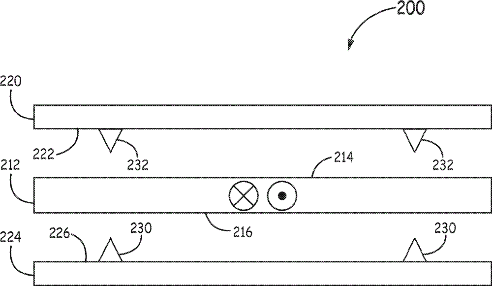
[0058] Example 1 includes a MEMS device comprising: at least one proof mass having a first surface and an opposing second surface, the proof mass configured to have a first voltage and motor movement in a first horizontal direction; a sensing plate separated from the proof mass by a first sensing gap, the first sensing plate having an inner surface facing the first surface of the proof mass and having a voltage different from the first voltage a second voltage; and a first set of stop structures on the inner surface of the first sense plate and electrically isolated from the first sense plate, the first set of stop structures configured to prevent The inner surface of the first sensing plate is in vertical contact with the proof mass, and the first set of stop structures has substantially the same voltage as that of the proof mass; wherein the first set The stop structure is dimensioned to minimize energy exchange when in contact with the proof mass during an impact or acceler...

example 2

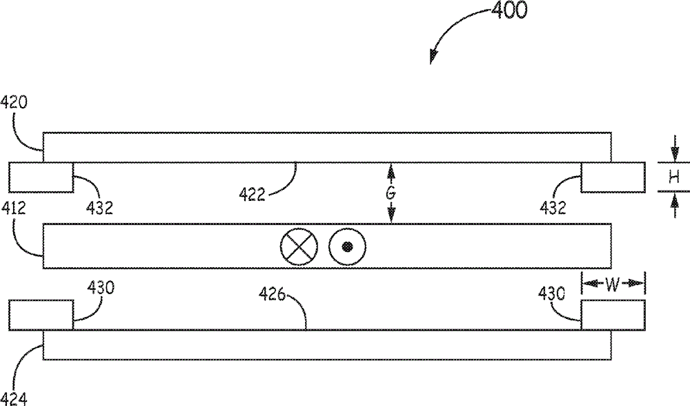
[0059] Example 2 includes the MEMS device of Example 1, further comprising: a second sense plate separated from the proof mass by a second sense gap, the second sense plate having the opposing an inner surface of the second surface and having a third voltage different from the first and second voltages; and a second set of stop structures located on the inner surface of the second sensor plate and electrically isolated For the second sensing plate, the second set of stop structures is configured to prevent the inner surface of the second sensing plate from contacting the proof mass in the vertical direction, and the second set of stop structures having substantially the same voltage as the proof mass; wherein the second set of stop structures are sized to minimize energy exchange when in contact with the proof mass during an impact or acceleration event.

example 3

[0060] Example 3 includes the MEMS device of Example 2, wherein the first and second sets of stop structures are each substantially the same size and shape.


PUM


Abstract

A micro-electro-mechanical systems (MEMS) device comprises at least one proof mass configured to have a first voltage and a motor motion in a first horizontal direction. At least one sense plate is separated from the proof mass by a sense gap, with the sense plate having an inner surface facing the proof mass and a second voltage different than the first voltage. A set of stop structures are on the inner surface of the sense plate and are electrically isolated from the sense plate. The stop structures are configured to prevent contact of the inner surface of the sense plate with the proof mass in a vertical direction. The stop structures have substantially the same voltage as that of the proof mass, and are dimensioned to minimize energy exchange upon contact with the proof mass during a shock or acceleration event.

Description

Background technique [0001] Microelectromechanical systems (MEMS) devices may include various sensors, such as gyroscopes and accelerometers, which may be implemented in various control systems and inertial navigation applications, such as inertial measurement units (IMUs). A MEMS gyroscope or accelerometer may include a microstructured sensing element, such as a proof mass, interposed between a pair of sensing plates to form a capacitive sensor. [0002] Operation of MEMS sensors may be disturbed or prevented when subjected to very high levels of shock or vibration. One identified cause of this operational failure is contact between the proof mass and one or both of the sense plates that the proof mass oscillates. When contact of the proof mass to the sensor plate occurs, an exchange of charge occurs and may result in disturbance or loss of the sensor signal. [0003] Currently, MEMS sensors rely primarily on proof-mass support springs that have stiffness in a direction per...

Claims


Application Information

Patent Timeline
IPC IPC(8): G01P1/00G01P15/08
CPCG01C19/574G01C25/00G01C19/56G01C19/5783G01P2015/0871Y10T29/49002
Inventor T.J.汉森M.W.韦伯M.C.格伦D.A.卡尼克
Owner HONEYWELL INT INC
Why Eureka
Try Eureka