
Large field of view fast two-dimensional scanning mirror installation structure

A two-dimensional scanning mirror and installation structure technology, applied in the field of terahertz detection and imaging, can solve the problems of long imaging time, difficult high-speed scanning, difficult imaging detection of moving targets, etc., and achieve the effect of reducing the moment of inertia

Active Publication Date: 2017-01-18
NO 50 RES INST OF CHINA ELECTRONICS TECH GRP
View PDF4 Cites 0 Cited by
  • Summary
  • Abstract
  • Description
  • Claims
  • Application Information

AI Technical Summary

Problems solved by technology

The existing frame-type scanning structure directly driven by the motor is mostly used in large field of view and low-speed occasions. Direct drive has high requirements on the motor, and it is difficult to achieve high-speed scanning. The imaging time is long, and it is difficult to realize the imaging detection of moving targets.
However, although the existing fast scanning mirrors driven by piezoelectric ceramics or voice coil motors have a relatively high scanning speed, their field of view is relatively small (usually only a few minutes), which is far from meeting the needs of terahertz imaging detection technology under large field of view. needs

Method used


Image

  • Large field of view fast two-dimensional scanning mirror installation structure
  • Large field of view fast two-dimensional scanning mirror installation structure

Examples


Embodiment Construction

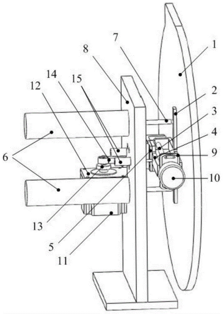
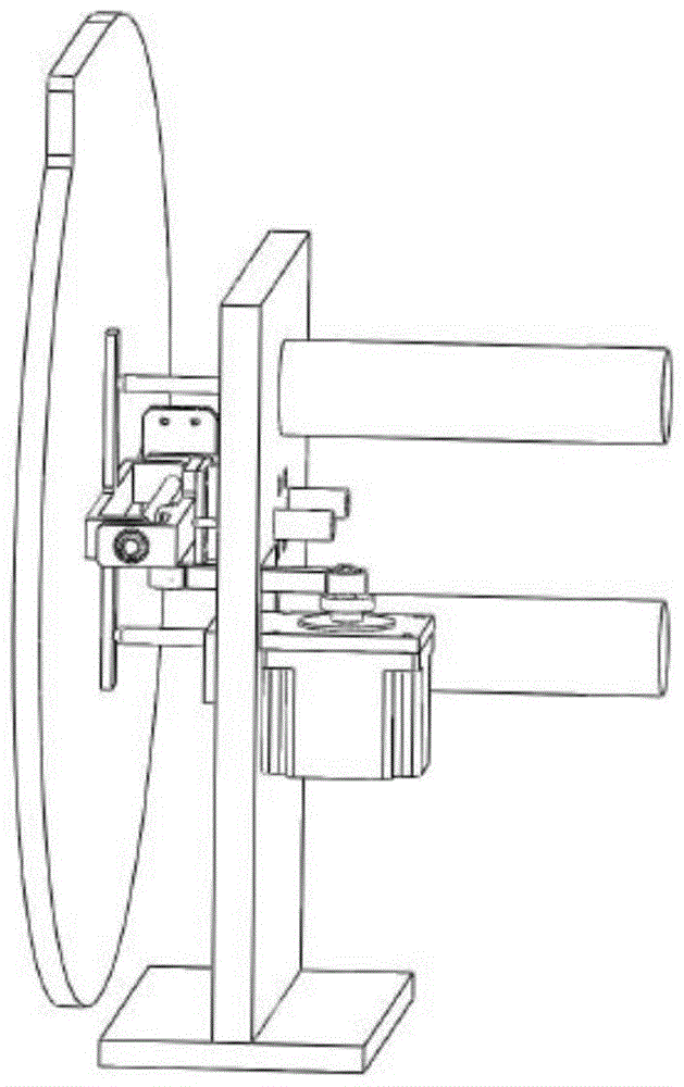
[0020] Attached below figure 1 with figure 2 The specific implementation of an embodiment of the large field of view fast scanning mirror of the present invention is described in detail:

[0021] Such as figure 1 with figure 2 As shown, the scanning mirror 1 is connected by the scanning mirror support frame 2 bonded on its back plate through the rotation joint formed between the pitch axis 3 and the pitch axis support frame 4, and the scanning mirror support frame 2 and the pitch axis 3 are connected by a tight The fixed screw is fixedly connected; the pitch axis support frame 4 is fixed on the bracket 8 through a one-dimensional flexible hinge 5, and the two voice coil motors 6 distributed up and down are pushed by linear motions with the same speed and opposite directions through the spherical actuator 7 installed on the shaft end The scanning mirror 1 swings around the pitch axis 3; the azimuth drive motor 11 fixed on the bracket 8 through the azimuth drive motor mount...


PUM


Abstract

The invention provides a large-view-field rapid two-dimensional scanning mirror mounting structure. The large-view-field rapid two-dimensional scanning mirror mounting structure comprises upper and lower pitching driving motors which are symmetrical relative to a long axis of a scanning mirror at a zero position, wherein the two pitching driving motors drive the scanning mirror to scan in a pitching direction by the movement with the same speed and opposite directions; the large-view-field rapid two-dimensional scanning mirror mounting structure further comprises an azimuth driving motor, an angle sensor and two linear displacement sensors; the azimuth driving motor is used for driving a crank connection rod mechanism so as to drive the scanning mirror to scan in an azimuth direction; the angle sensor is used for realizing the measurement of a pitching angle of the scanning mirror; the two linear displacement sensors are used for differentially measuring linear displacement when a pitching shaft supporting frame rotates and indirectly measuring an azimuth rotary angle of the scanning mirror. Compared with an existing two-dimensional scanning machine structure, large-view-field scanning can be realized while high-speed scanning is realized, so that a terahertz imaging detection system is practical to the application to public place safety inspection.

Description

technical field [0001] The invention belongs to the technical field of terahertz detection and imaging, and relates to the problem of increasing the scanning speed under the condition of a large detection field of view in detection and imaging, in particular to a fast two-dimensional scanning mirror installation structure with a large field of view. Background technique [0002] In the field of terahertz imaging detection, due to the limitation of the field of view of the optical system itself and the key technology of the large area array terahertz detector has not yet broken through at this stage, it is necessary to use a mechanically driven two-dimensional scanning mechanism to expand the field of view of the system. In order to complete the rapid scanning imaging of the target. The existing frame-type scanning structures directly driven by motors are mostly used in large field of view and low-speed situations. Direct drive has high requirements on motors, making it diffi...

Claims


Application Information

Patent Timeline
Patent Type & Authority Patents(China)
IPC IPC(8): G02B26/10
Inventor 关冉侯丽伟谢巍周德亮王兵兵刘素芳臧元章邹锶俞旭辉王晓东鲁斌汪瑞
Owner NO 50 RES INST OF CHINA ELECTRONICS TECH GRP
Learn More