Ink spraying type liquid crystal coating machine and exhaust method for nozzle of coating machine

An inkjet and coating machine technology, applied in the direction of nonlinear optics, instruments, optics, etc., can solve the problems of lower production line production efficiency, increased nozzle exhaust time, liquid crystal waste, etc., to improve production efficiency and increase emissions speed, loss reduction effect

Active Publication Date: 2015-02-11
HEFEI XINSHENG OPTOELECTRONICS TECH CO LTD +1
View PDF1 Cites 5 Cited by
  • Summary
  • Abstract
  • Description
  • Claims
  • Application Information

AI Technical Summary

Problems solved by technology

[0005] However, during the above exhaust process, the liquid crystal will be discharged from the outlet of the nozzle 06, resulting in waste of liquid crystal, and the liquid crystal in the injector 02 may not be able to discharge the gas in the nozzle 06 at one time, and the injector 02 needs to be repeatedly extracted from the liquid storage device 01. Liquid crystal requires multiple opening and closing of the control valves, which increases the exhaust time of the nozzle and reduces the production efficiency of the production line

Method used


Image

  • Ink spraying type liquid crystal coating machine and exhaust method for nozzle of coating machine
  • Ink spraying type liquid crystal coating machine and exhaust method for nozzle of coating machine
  • Ink spraying type liquid crystal coating machine and exhaust method for nozzle of coating machine

Examples


Embodiment 1

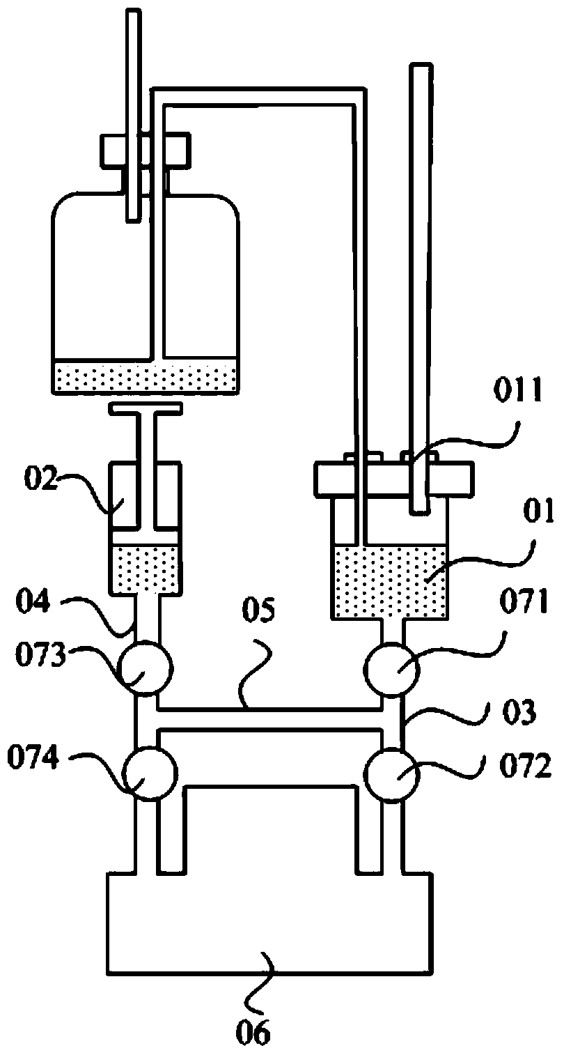
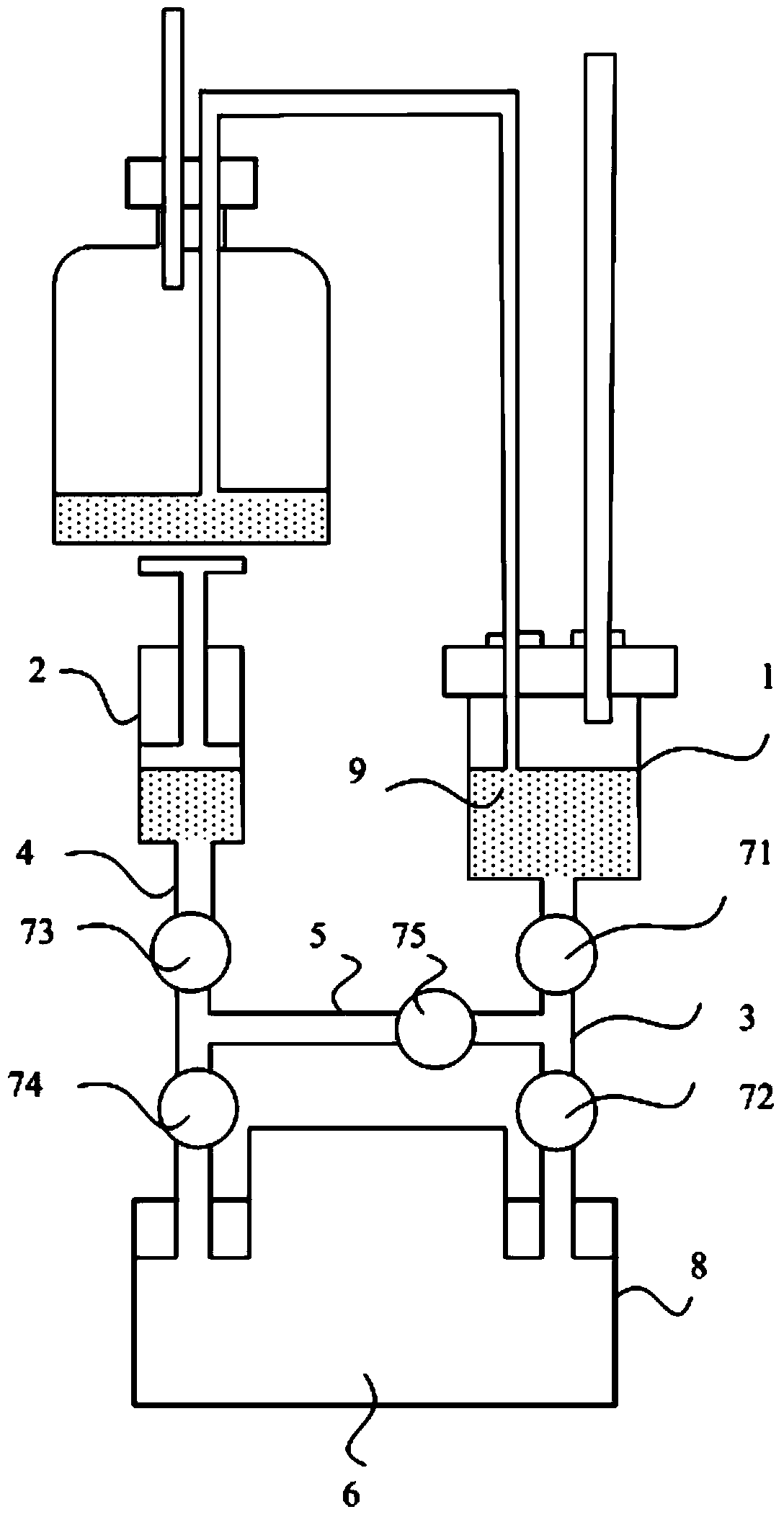
[0048] Such as figure 2 as shown, figure 2 The schematic diagram of the structure of the liquid crystal inkjet coating machine provided by the embodiment of the present invention, the liquid crystal inkjet coating machine provided by the present invention includes: a liquid storage device 1, an injector 2 on one side of the liquid storage device 1, and a nozzle 6 , the first communication pipeline 3 for connecting the liquid crystal outlet of the liquid storage device 1 with one opening of the nozzle 6, the second communication pipeline 4 for connecting the liquid crystal outlet of the injector 2 with the other opening of the nozzle 6, The third communication pipeline 5 for connecting the first communication pipeline 3 with the second communication pipeline 4, the first control valve 71 and the second control valve 72 arranged on the first communication pipeline 3 are arranged on the second communication pipeline 5 The third control valve 73 and the fourth control valve 74 ...

Embodiment 2

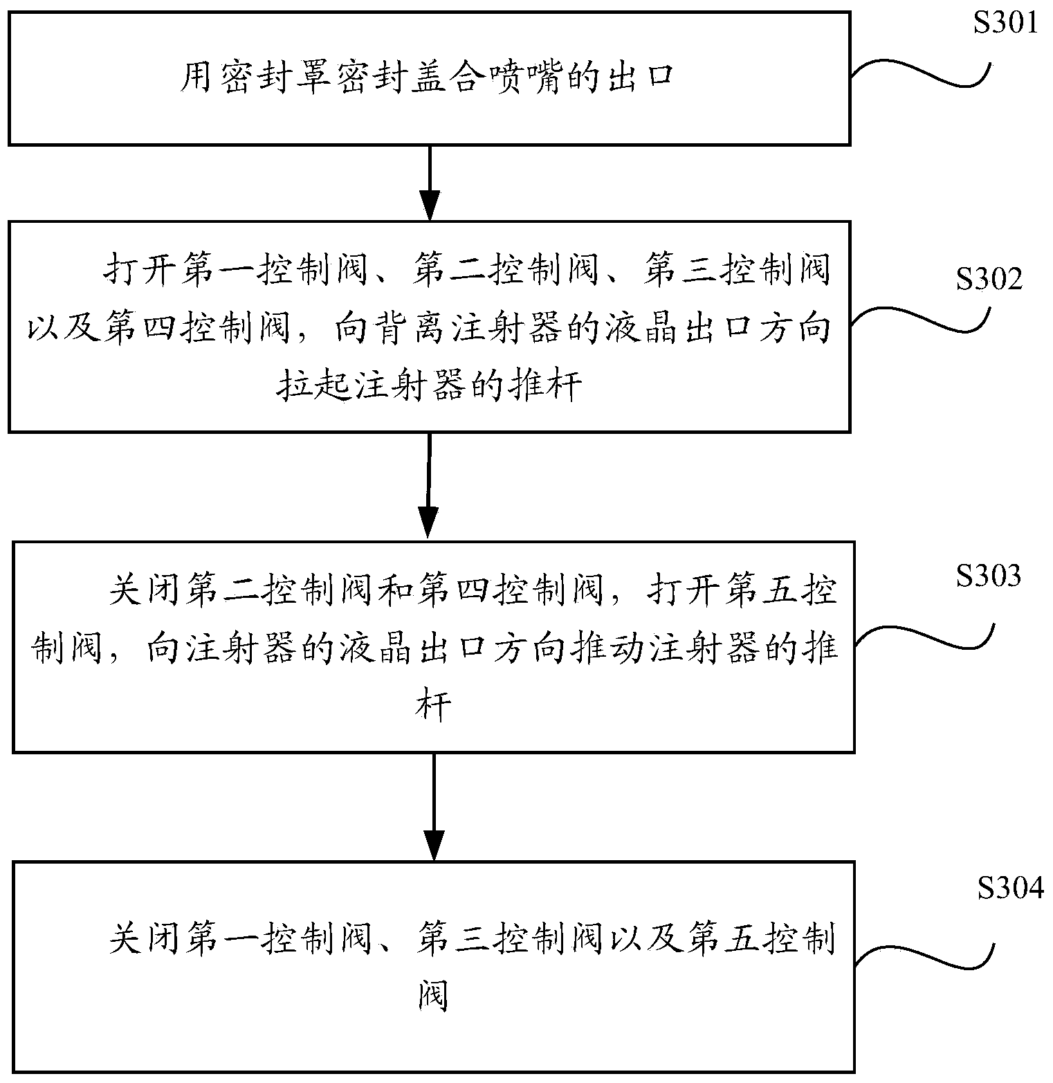
[0069] Such as image 3 as shown, image 3 The flow chart of the exhaust method of the nozzle of the liquid crystal inkjet coating machine provided by the embodiment of the present invention, the embodiment of the present invention provides an inkjet coating machine applied to any one of the above-mentioned embodiment one Exhaust methods for nozzles, including:

[0070] Step S301: sealing at least the outlet of the nozzle with a sealing cover;

[0071] Step S302: Open the first control valve, the second control valve, the third control valve and the fourth control valve, pull up the push rod of the syringe in the direction away from the liquid crystal outlet of the syringe, and the liquid crystal in the liquid storage device will pass through the first communication channel in turn. The pipeline, the nozzle and the second communication pipeline enter the syringe, and when the liquid crystal passes through the nozzle, the gas in the nozzle can be discharged into the syringe t...


PUM


Abstract

The invention discloses an ink spraying type liquid crystal coating machine and an exhaust method for the nozzle of the coating machine, and aims to reduce the liquid crystal loss, and accelerate the exhaust speed of gas in the nozzle of the coating machine. The coating machine comprises a liquid storage device, an injector, the nozzle, a first communicating pipeline, a second communicating pipeline, a third communicating pipeline, a first control valve, a second control valve, a third control valve, and a fourth control valve, and further comprises a seal cover for at least hermetically covering the outlet of the nozzle, and a fifth control valve arranged on the third communicating pipeline, wherein when the first to fourth control valves are all opened and the fifth control valve is closed, the injector, the nozzle and the liquid storage device are communicated with one another; when the first control valve, the fifth control valve and the third control valve are all opened and both the second control valve and the fourth control valve are closed, the injector and the liquid storage device are communicated with each other.

Description

technical field [0001] The invention relates to the technical field of liquid crystal display preparation, in particular to a liquid crystal inkjet coating machine and an exhaust method for nozzles thereof. Background technique [0002] In the liquid crystal panel preparation process, it is necessary to inject liquid crystal molecules between two opposite substrates, and at this time, a liquid crystal inkjet coating machine is required. [0003] Such as figure 1 as shown, figure 1 It is a structural schematic diagram of a liquid crystal inkjet coating machine in the prior art. The liquid crystal inkjet coating machine in the prior art mainly includes: a liquid storage device 01, and an injector 02 arranged on one side of the liquid storage device 01 , the first communication pipeline 03, the second communication pipeline 04, the third communication pipeline 05, the nozzle 06, the first control valve 071, the second control valve 072, the third control valve 073, and the fo...

Claims


Application Information

Patent Timeline
Patent Type & Authority Applications(China)
IPC IPC(8): G02F1/1341
CPCG02F1/1341G02F1/13415
Inventor 方跃郭知广唐大虎王成功
Owner HEFEI XINSHENG OPTOELECTRONICS TECH CO LTD
Why Eureka
Try Eureka