Humiture autoregulation network monitoring system

An automatic adjustment and network monitoring technology, applied in the direction of control/regulation system, non-electric variable control, comprehensive factory control, etc., can solve the problems of equipment damage, poor ventilation, easy damage, etc., and achieve the effect of improving the service life

An automatic adjustment and network monitoring technology, applied in the direction of control/regulation system, non-electric variable control, comprehensive factory control, etc., can solve the problems of equipment damage, poor ventilation, easy damage, etc., and achieve the effect of improving the service life

CN104345754AInactive Publication Date: 2015-02-11TIANJIN CHANGZHENG BOSHENG TECH

Image

  • Humiture autoregulation network monitoring system

Examples


Embodiment Construction

[0013] Below in conjunction with the examples, the present invention is further described, the following examples are illustrative, not limiting, and the protection scope of the present invention cannot be limited by the following examples.

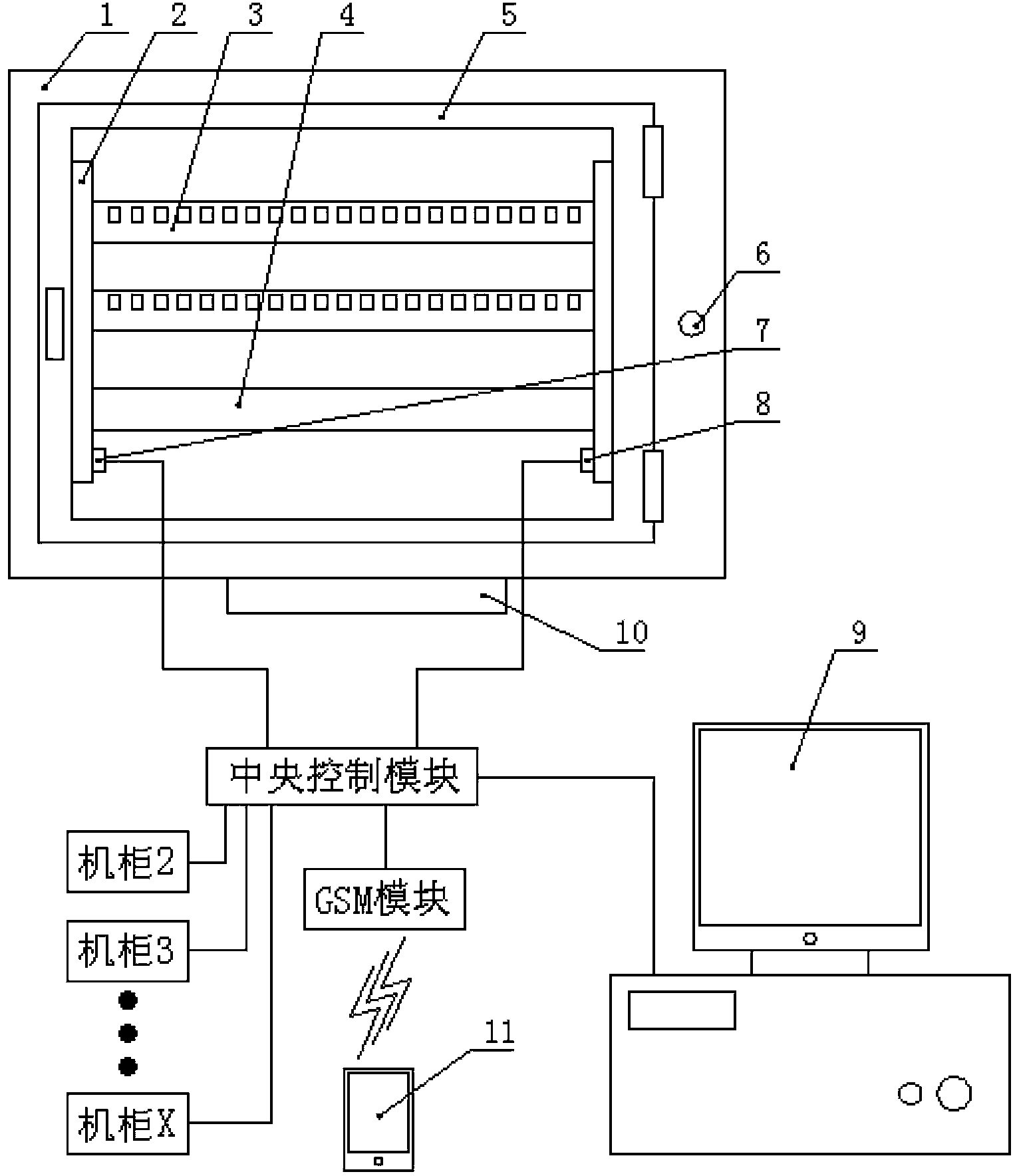
[0014] A network monitoring system with automatic temperature and humidity adjustment, such as figure 1 As shown, a plurality of cabinets 1 are included, and cabinet doors 5 are installed at the front end of each cabinet, and installation frames 2 are fixed on the two side walls inside the cabinet, and multiple network devices are installed between the two installation frames. The innovation of the present invention lies in : a temperature sensor 7 and a humidity sensor 8 are respectively installed on the mounting frame, the output ends of the temperature sensor and the humidity sensor are connected to the input / output interface of the central control module installed in the cabinet, and the input / output interface of the central control m...


PUM


Abstract

The invention relates to a humiture autoregulation network monitoring system. Temperature sensors and humidity sensors are installed respectively on mounting racks. Output ends of the temperature sensors and the humidity sensors are connected with input / output interfaces of central control modules installed in cabinets. The input / output interfaces of the central control modules are connected with control ends of exhaust fans installed on the side walls of the cabinets. In the system, network devices such as a plurality of switches and routers are installed in all of the plurality of cabinets. A temperature sensor and a humidity sensor are installed in each cabinet. The detection results are uploaded to an upper computer through network cables and uploaded to handsets of polling personnel in a wireless method through a GSM module at the same time so that the temperature and humidity in each cabinet can be seen by detection personnel at any time. When the humidity and temperature exceed limits, the exhaust fans in the cabinets start to complete heat radiation and dehumidification and when the temperatures in the cabinets are reduced, the exhaust fans stop operating so that the service lives of the exhaust fans are improved.

Description

technical field [0001] The invention belongs to network equipment technology field , especially a network monitoring system with automatic temperature and humidity adjustment. Background technique [0002] In the office or in the home life, the network is indispensable, and it constitutes the main channel of internal or external communication. Routers, optical fibers, switches and other devices are commonly used in the network. These devices connect the central office and end users through optical fibers or network cables, so that information and data can be transmitted internally or between internal and external. In newly built buildings, space for installing the above-mentioned equipment is generally reserved. Firstly, the cabinets are placed in these spaces, and then distribution frames, switches, routers and other equipment are installed on the installation racks in the cabinets, and finally locked. Only the valve of the cabinet can be used. [0003] In the network tr...

Claims


Application Information

Patent Timeline
11 Feb 2015
Publication
CN104345754A
IPC
G05D27/02; G05B19/418
CPC
Y02P90/02
Inventors
解文鸿