
Peeling apparatus and peeling method

A peeling device and release layer technology, applied in chemical instruments and methods, optics, lamination auxiliary operations, etc., can solve the problems of laser peeling equipment cost, high maintenance cost, time-consuming glass process, etc.

Inactive Publication Date: 2015-02-11
EVERDISPLAY OPTRONICS (SHANGHAI) CO LTD
View PDF12 Cites 28 Cited by
  • Summary
  • Abstract
  • Description
  • Claims
  • Application Information

AI Technical Summary

Problems solved by technology

[0003] The glass process is very time-consuming due to the need to scan with a laser. In addition, the cost of laser stripping equipment and maintenance costs are high

Method used


Image

  • Peeling apparatus and peeling method
  • Peeling apparatus and peeling method
  • Peeling apparatus and peeling method

Examples


Embodiment Construction

[0021] Example embodiments will now be described more fully with reference to the accompanying drawings. Example embodiments may, however, be embodied in many forms and should not be construed as limited to the embodiments set forth herein; rather, these embodiments are provided so that this disclosure will be thorough and complete, and will fully convey the concept of example embodiments to those skilled in the art. In the drawings, the thickness of regions and layers are exaggerated for clarity. The same reference numerals in the drawings denote the same or similar structures, and thus their detailed descriptions will be omitted.

[0022] The described features, structures, or characteristics may be combined in any suitable manner in one or more embodiments. In the following description, numerous specific details are provided in order to give a thorough understanding of embodiments of the present disclosure. However, one skilled in the art will appreciate that the technic...


PUM


Abstract

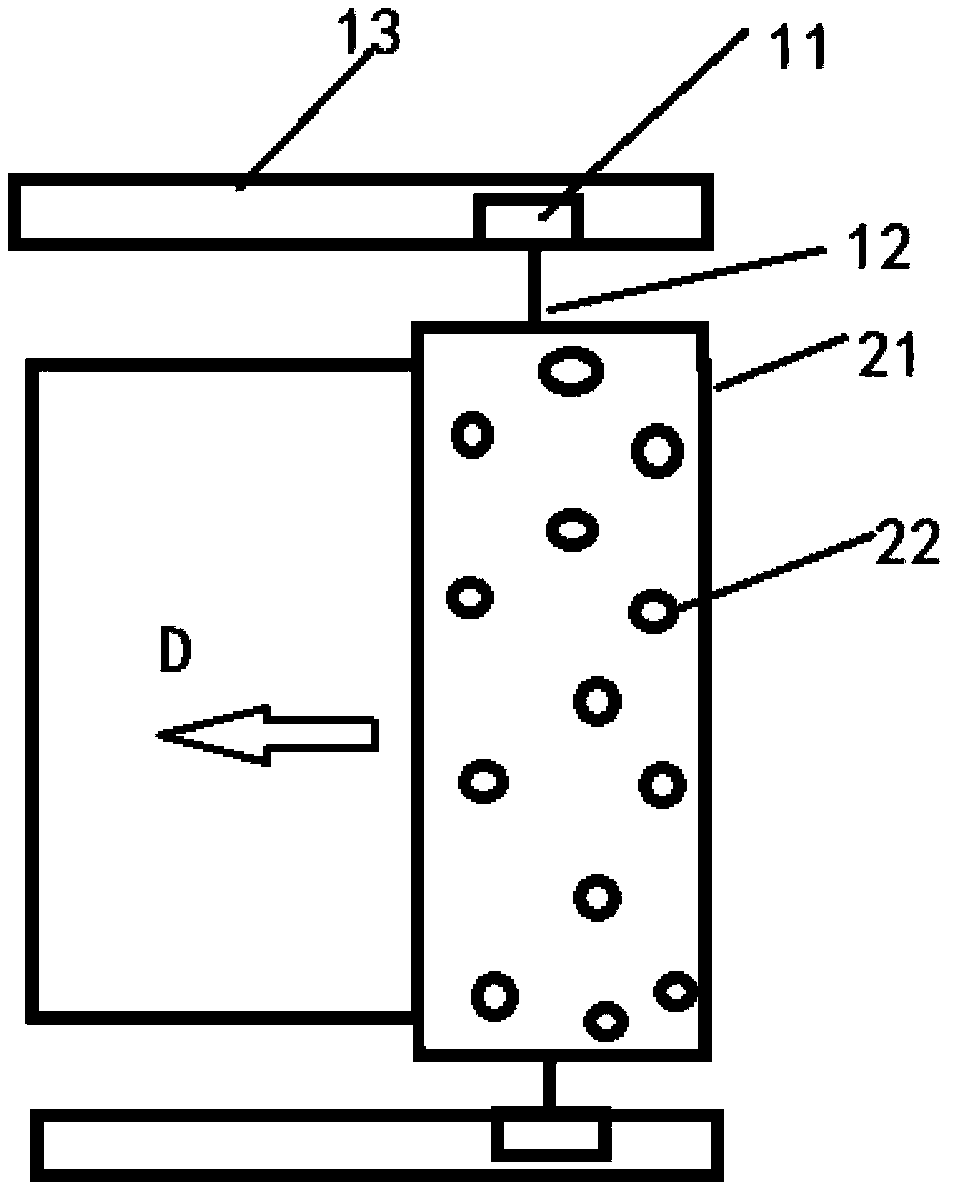
A stripping device is provided which comprises: a wire cutter comprising a moving part and a cutting part connected to the moving part in such a manner that the moving part is able to drive the cutting part linearly; and an attracting wheel comprising a body part adapted to be movably mounted on the flexible substrate so that the body part is able to roll on the flexible substrate and an adsorption part connected to the body part to generate adsorption force to securely attach a part of the flexible substrate as the result of movement of the cutting part.

Description

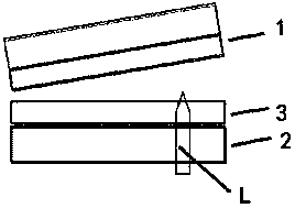
technical field [0001] The present disclosure generally relates to a peeling device and a peeling method, and in particular, to a device and a peeling method for peeling a flexible substrate from a layer bonded thereto. Background technique [0002] Usually, the flexible substrate 1 and the glass substrate 2 are bonded together through the release layer 3, such as figure 1 As shown, in order to peel off the flexible substrate from the glass substrate, the current method is laser lift-off (Laser lift-off). figure 2 As shown, the laser L is used to scan the release layer material between the flexible substrate 1 and the glass substrate 2, and high energy is given to break the bond between the release layer 3 and the flexible substrate 1 and destroy the bond between the flexible substrate 1 and the release layer 3. bonding, so that the flexible substrate 1 is peeled off. [0003] Since laser scanning is required, the glass process is very time-consuming. In addition, the cos...

Claims


Application Information

Patent Timeline
Patent Type & Authority Applications(China)
IPC IPC(8): H01L21/67H01L21/68G02F1/1333B32B38/10
CPCB26D7/0006B26D1/547B26D7/1863B26D3/28B26D5/08B26D7/018Y10T83/0448Y10T83/2196
Inventor 郑功侑黄添旺
Owner EVERDISPLAY OPTRONICS (SHANGHAI) CO LTD
Learn More