
Ammonia tail gas recycling method and system

A recovery method and tail gas technology, which is applied in the field of ammonia tail gas recovery and utilization, can solve problems such as the need for improvement in the recovery method of ammonia-containing tail gas, difficult treatment costs of dilute ammonia water, and low concentration of ammonia water, so as to maintain ammonia recovery rate and equipment operation stability The effect of high and high ammonia recovery

Active Publication Date: 2012-09-26
CHONGYI ZHANGYUAN TUNGSTEN
View PDF7 Cites 15 Cited by
  • Summary
  • Abstract
  • Description
  • Claims
  • Application Information

AI Technical Summary

Problems solved by technology

The first method is to condense the ammonia tail gas into dilute ammonia water, but due to the low concentration and large volume of ammonia water, it can only be partially returned to the main process for use, and most of the dilute ammonia water is difficult to handle or the treatment cost is extremely high
The second method is to use water or acidic solution to spray and absorb the ammonia tail gas into the corresponding ammonia nitrogen solution, and then concentrate it by evaporation for recycling, but it has the disadvantages of high cost and low efficiency.
[0003] Therefore, the current recovery methods for ammonia-containing tail gas still need to be improved

Method used


Image

  • Ammonia tail gas recycling method and system
  • Ammonia tail gas recycling method and system

Examples


Embodiment 1

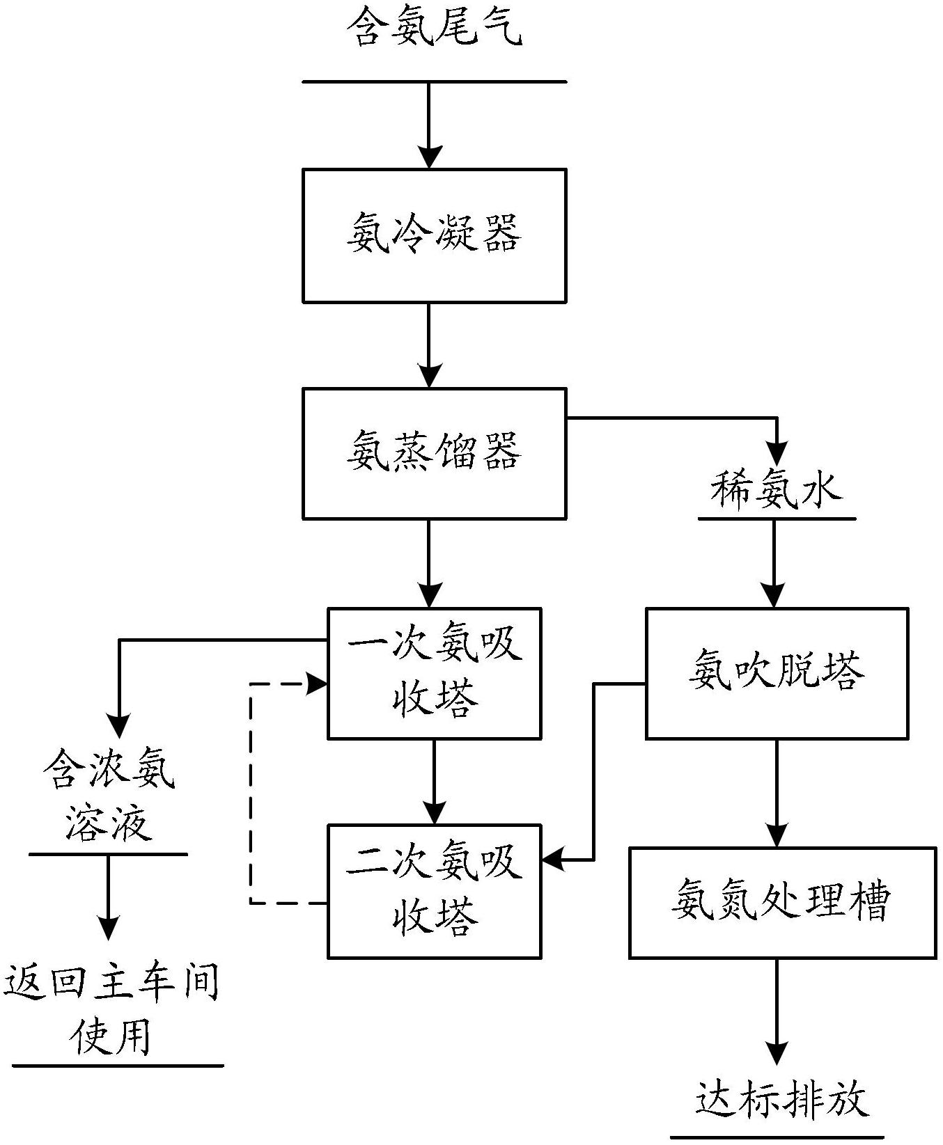
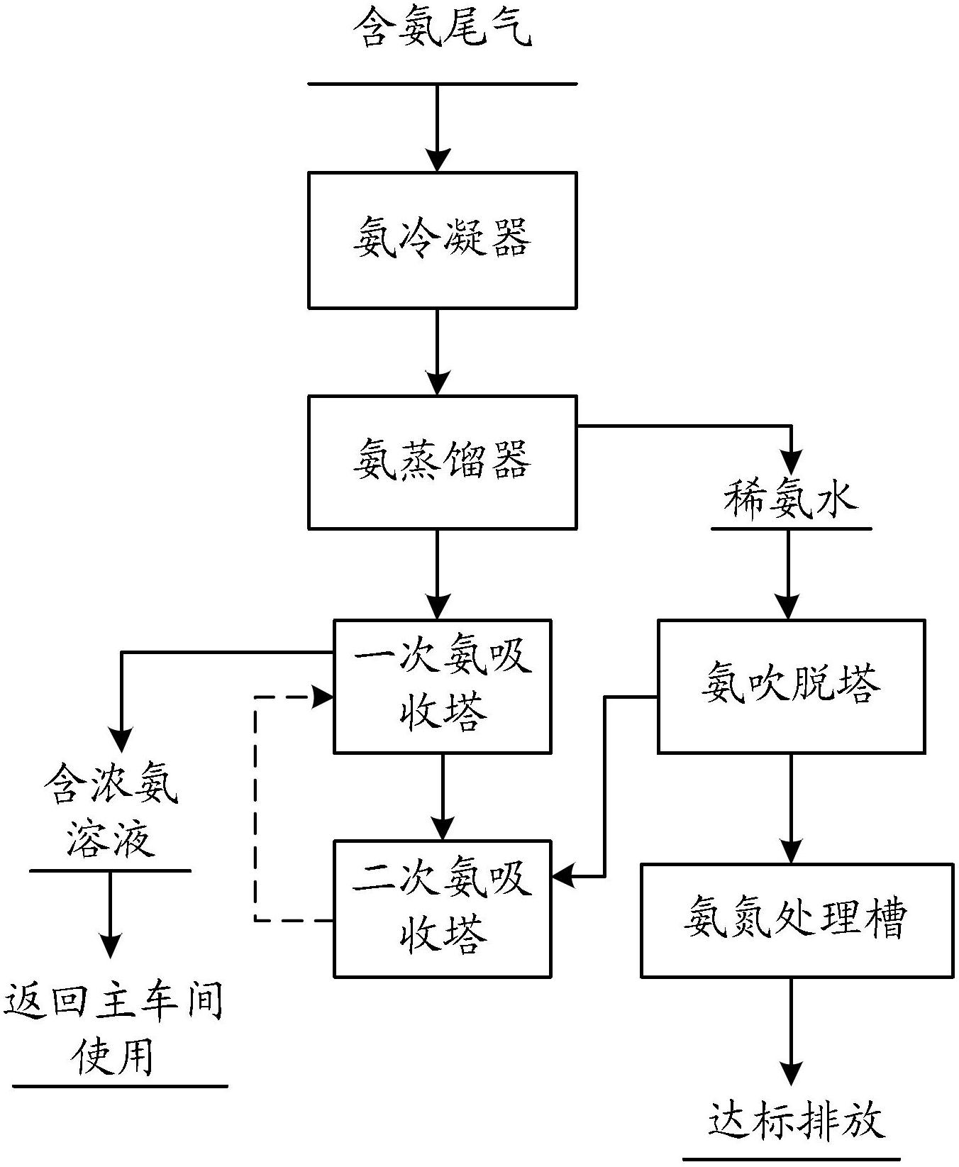
[0037] 10m 3 Evaporation and crystallization pot (feed volume is 4m 3 ~7m 3 ), the feed ammonium tungstate solution is 6m 3 , WO 3 =250g / L, OH - =2mol / L. Condensation by condenser gives 3.4m 3 Dilute ammonia water, the ammonia nitrogen concentration is 8g / L; Dilute ammonia water is distilled under pressure at 100°C in a distillation pot, and the volume of the distilled liquid is 3.2m 3 , the concentration of liquid ammonia nitrogen after distillation is 4g / L; after distillation, the liquid is blown off by a dissolved air pump, and the concentration of ammonia nitrogen after blowing off is 900mg / L, and the blowing off rate is 77.5%; Deep removal, the concentration of ammonia nitrogen after removal is 7mg / L, and the removal rate is 99.22%.

[0038] Perform a spray cycle absorption on the condensed ammonia tail gas and distilled ammonia water to obtain 3.1m 3 One-time absorption of ammonia nitrogen solution, the concentration of ammonia nitrogen is 80g / L, which is directl...

Embodiment 2

[0041] 10m 3 Evaporation and crystallization pot (feed volume is 4m 3 ~7m 3 ), the feed ammonium tungstate solution is 4m 3 , WO 3 =250g / L, OH - =2mol / L. Condensed by condenser to get 2.35m 3 Dilute ammonia water, the ammonia nitrogen concentration is 7g / L; the dilute ammonia water is distilled under pressure at 98°C in a distillation pot, and the volume of the distilled liquid is 2.2m 3 , the concentration of liquid ammonia nitrogen after distillation is 3.7g / L; the liquid after distillation is blown off by a dissolved air pump, the concentration of ammonia nitrogen after blowing off is 700mg / L, and the stripping rate is 81%; finally, the liquid after blowing off is treated with ammonia nitrogen remover Ammonia nitrogen is deeply removed, the concentration of ammonia nitrogen after removal is 5mg / L, and the removal rate is 99.28%.

[0042] Perform a spray cycle absorption on the condensed ammonia tail gas and distilled ammonia water to obtain 2.1m 3 One-time absorptio...


PUM

PropertyMeasurementUnit
concentrationaaaaaaaaaa

Abstract

The invention relates to an ammonia tail gas recycling method and system. The method comprises condensing tail gas containing ammonia so as to obtain dilute ammonia water and condensed ammonia tail gas; distilling the dilute ammonia water to obtain ammonia gas, water and distilled liquid; and subjecting the condensed ammonia tail gas and the ammonia gas to first spraying absorption by use of low-concentration ammonia chloride solution to obtain first spray ammonia nitrogen solution and first spray residual ammonia tail gas, wherein the ammonia nitrogen concentration in the ammonia nitrogen solution is not lower than 70g / L. With the inventive method, ammonia-containing tail gas can be effectively recycled.

Description

technical field [0001] The invention belongs to the field of tungsten concentrate smelting. More specifically, the present invention relates to a method and system for recycling ammonia tail gas. Background technique [0002] At present, a large amount of ammonia tail gas will be produced in the process of tungsten hydrometallurgy, and about 200 kg of ammonia gas will be produced for every ton of ammonium paratungstate produced. If the ammonia gas is discharged directly, it will increase the production cost and pollute the environment. At present, the following two methods are mainly used to recycle ammonia tail gas. The first method is to condense the ammonia tail gas into dilute ammonia water. However, due to the low concentration and large volume of ammonia water, it can only be partially returned to the main process for use. Most of the dilute ammonia water is difficult to handle or the treatment cost is extremely high. The second method is to use water or acidic solu...

Claims


Application Information

Patent Timeline
Patent Type & Authority Applications(China)
IPC IPC(8): B01D5/00B01D53/18C02F1/04
Inventor 徐国钻黄泽辉李飞许礼楷谢甫旭
Owner CHONGYI ZHANGYUAN TUNGSTEN
Learn More