Nursing toilet pan device

The technology of a toilet device and a toilet box, which is applied to the field of patient care appliances, can solve the problems of limited use environment, splashing in the toilet when the patient cannot be flushed, etc., and achieve the effects of improving the working environment, improving the happiness index, and reducing labor intensity.

Active Publication Date: 2015-02-18
GUANGXI CHANGXIN TECH
View PDF7 Cites 5 Cited by
  • Summary
  • Abstract
  • Description
  • Claims
  • Application Information

AI Technical Summary

Problems solved by technology

[0003] The purpose of the present invention is to solve the problem that the existing toilet is a fixed structure, and most of the mobile toilets suitable for patients are placed under the bench, hospital bed and wheelchair. The environment is limited, and toilet paper needs to be wiped after defecation, which has the disadvantages of being unclean and unable to rinse; especially when the patient goes out and sits in a wheelchair, it is more inconvenient to use, and a nursing toilet device is provided

Method used


Image

  • Nursing toilet pan device
  • Nursing toilet pan device
  • Nursing toilet pan device

Examples


specific Embodiment approach 1

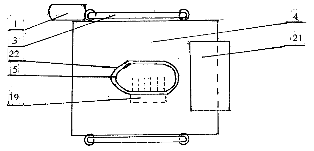
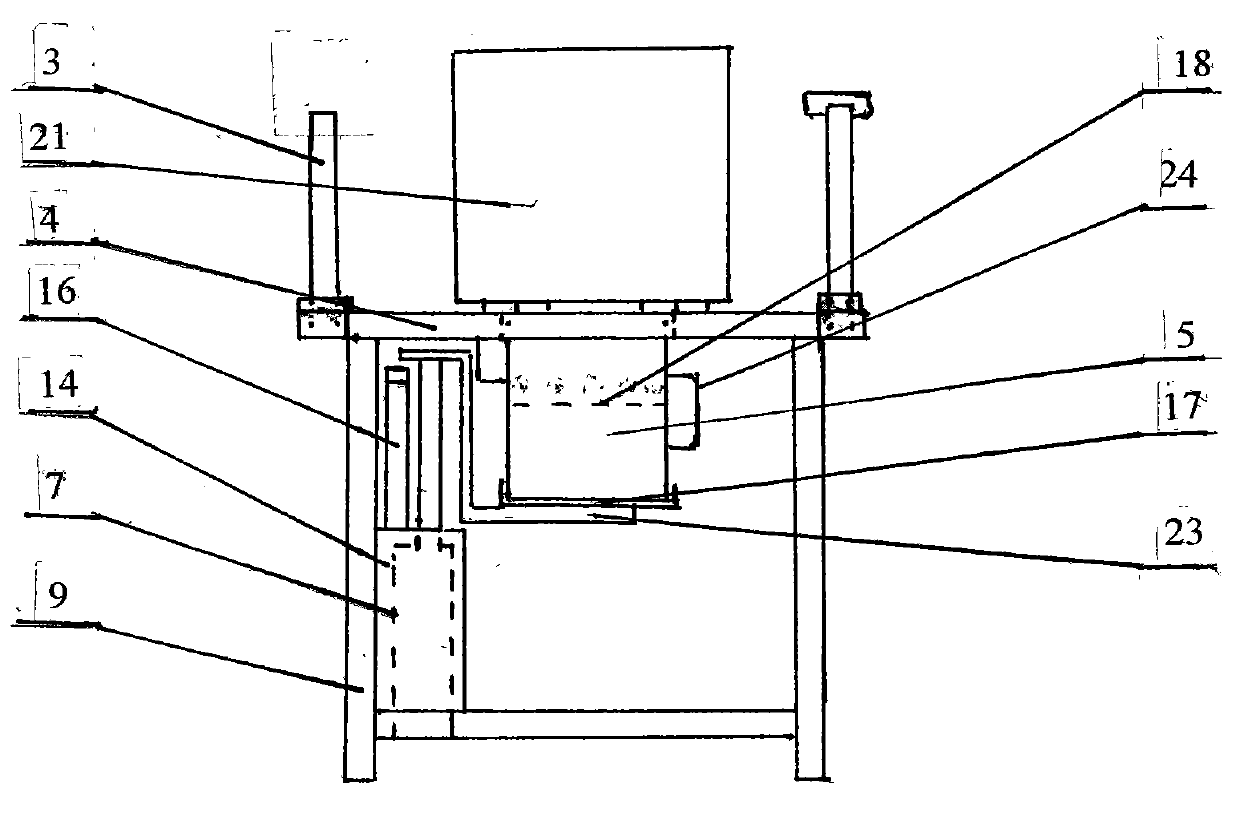
[0006] Specific implementation mode one: (see Figure 1 ~ Figure 3 , Figure 7 , Figure 8 ) This embodiment consists of a controller 1, an upper panel 4, a toilet box 5, a hot air pipe 6, an electric push-pull rod assembly 7, a hot air blower 8, a frame 9, a magnetizer 10, a temperature controller 11, a submersible pump 12, a heating Device 13, water tank 14, warm water pipe 15, water pipe 16, tray 17, foam height line 18, function box 19, box opening 22, tray bracket 23, box handle 24, porous water spray assembly 33, box opening Hole 34, hot air spout 35 is formed; The upper panel 4 is provided with the toilet box opening 22, and the bottom of the upper panel 4 is provided with the toilet box 5, and the toilet box 5 is arranged on the top of the tray 17, and the tray bracket 23 is fixed below the tray 17. One end, the other end of the tray support 23 is fixed above the extended end of the electric push-pull rod assembly 7, the electric push-pull rod assembly 7 is fixed on ...

specific Embodiment approach 2

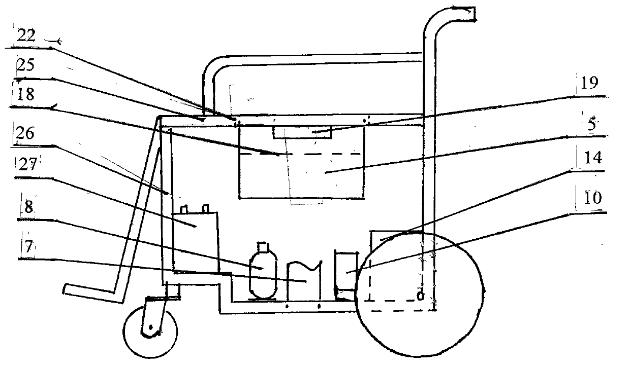
[0007] Specific implementation mode two: (see Figure 1 ~ Figure 4 , Figure 6 ~ Figure 8 ) The difference between this embodiment and the specific embodiment one is that the toilet box 5 is arranged below the wheelchair panel 25, the wheelchair panel 25 is provided with a toilet box opening 22, and the wheelchair panel 25 is fixed with a function box 19 below the wheelchair frame 26. Battery 27, electric push-pull rod assembly 7, hot air blower 8, magnetizer 10, water tank 14 are fixed inside. The opening blocking plate 30 of the toilet box is fixed as a whole with the column 31 and the blocking plate base 32 , and the blocking plate base 32 is arranged on the tray 17 . Other compositions and connection methods are the same as those in Embodiment 1.

specific Embodiment approach 3

[0008] Specific implementation mode three: (see Figure 1 ~ Figure 3 , Figure 5 ~ Figure 8 ) The difference between this embodiment and the second embodiment is that the toilet box 5 is arranged below the bed panel 28, the bed panel 28 is provided with a toilet box opening 22, the functional box 19 is fixed below the hospital bed panel 28, and the bed frame 26 An electric push-pull rod assembly 7, a hot air blower 8, a magnetizer 10, and a water tank 14 are fixed inside. The opening blocking plate 30 of the toilet box is fixed as a whole with the column 31 and the blocking plate base 32 , and the blocking plate base 32 is arranged on the tray 17 . Other compositions and connection methods are the same as those in Embodiment 1.


PUM


Abstract

The invention relates to a nursing toilet pan device, which relates to a patient nursing device for medical rehabilitation mechanisms and families. The invention aims to solve the problems that the existing toilet pan device is of a fixed structure, most of movable toilet pan device suitable for patients are characterized in that a bed pan is put under a bench, a hospital bed and a wheelchair, splash exists when the patients pee or poop, smell is diffused to affect the environment, the service environment is limited, the patients need toilet paper to wipe after peeing or pooping, the defects of wiping uncleanness and non-flushing exist, and especially when the patients go out with the wheelchairs, the use is inconvenient. The nursing toilet pan device has the beneficial effects that the device is used as the movable toilet pan device to be used or is arranged on the hospital bed and the wheelchair in a pressing way, a bedpan can be moved up and down, the upper edge of the bedpan is tightly close to a hip part, and foam is added in the bedpan, so that the smell is controlled to be minimum without splash; after peeing and pooping, warm magnetic water can be used to spray, flush and sterilize, hot air is used to dry, the movement is convenient, the labor intensity of nursing is relieved, and the working environment of nursing is improved; when the nursing toilet pan device is used on the hospital bed and the wheelchair, the patients have no need to be moved, the bedpan is taken down from the lower part, a block board is replaced, and convenience is realized. The nursing toilet pan device is suitable for being used in hospitals, rehabilitation mechanisms, retirement organizations and families with patients.

Description

technical field [0001] The invention relates to a patient care appliance for medical rehabilitation institutions and families, in particular to a nursing toilet device, Background technique [0002] Existing toilets are of fixed structure, most of the mobile toilets suitable for patients are to put a bedpan under the bench, hospital bed and wheelchair. Wipe with toilet paper, there is the shortcoming that wiping is not clean, can't be rinsed; Especially when the patient goes out and sits in a wheelchair, it is more inconvenient to use. Contents of the invention [0003] The purpose of the present invention is to solve the problem that the existing toilet is a fixed structure, and most of the mobile toilets suitable for patients are placed under the bench, hospital bed and wheelchair. The environment is restricted, and toilet paper needs to be wiped after going to the toilet, which has the disadvantages of unclean wiping and inability to rinse; especially when the patient ...

Claims


Application Information

Patent Timeline
Patent Type & Authority Applications(China)
IPC IPC(8): A61G7/05A61G5/10
Inventor 宋大伟
Owner GUANGXI CHANGXIN TECH
Why Eureka
Try Eureka