Rotary vibrating screening machine

A technology of vibrating screen and screening machine, applied in the direction of filter screen, solid separation, grille, etc., can solve the problems of increased maintenance cost, frequent vibration frequency, increased production cost, etc., to ensure high efficiency, ensure continuity, improve The effect of production efficiency

Active Publication Date: 2015-02-18
ANHUI UNIV OF SCI & TECH
View PDF10 Cites 11 Cited by
  • Summary
  • Abstract
  • Description
  • Claims
  • Application Information

AI Technical Summary

Problems solved by technology

Because the vibration frequency of the vibrating motor is too frequent, there is a disadvantage of low screening efficiency when screening materials with large particle size differences, and only a single separation can be performed, resulting in low production efficiency.
Although there have been a series of improvements made to it in the follow-up, such as setting multiple screening machines in parallel through belt conveyors (Chinese patent document CN 103316842A), but it occupies a large area and requires a large investment, resulting in increased production costs; it is designed to be cylindrical. The multistage rotary grading screen (Chinese patent document CN 202490762U) with multistage filter areas increases the working load of the motor due to the gravity of the material itself; CN 103623995A) will increase the maintenance cost and increase the investment cost

Method used


Image

  • Rotary vibrating screening machine
  • Rotary vibrating screening machine
  • Rotary vibrating screening machine

Examples


Embodiment Construction

[0041] In order to make the object, technical solution and advantages of the present invention clearer, the present invention will be further described in detail below in conjunction with the accompanying drawings.

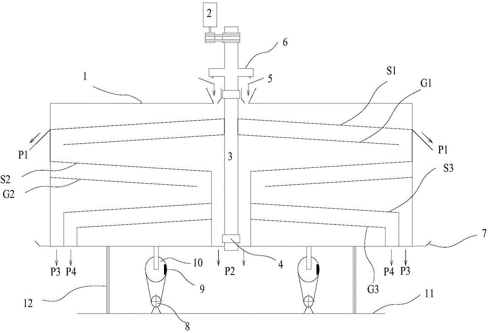
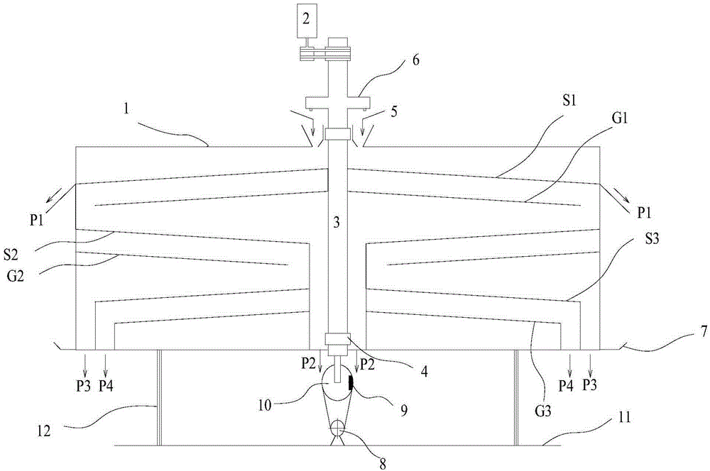
[0042] Such as figure 1 As shown, the rotary vibrating screening machine in this embodiment is a three-stage screening machine, that is, the screening machine contains three-stage screening groups.

[0043] The rotating shaft 3 is rotatably fixed on the support 7 (the support 7 is in figure 1 , 2 not fully drawn in), that is, if figure 1As shown, a bearing 4 is provided between the rotating shaft 3 and the bracket 7 , and the rotating shaft 3 forms a rotation fit with the bracket 7 through the bearing 4 ; the bracket 7 is fixed on the base 11 through the elastic support assembly 11 . The rotating motor 2 is fixed on the upper end of the bracket 7. Of course, the rotating motor 2 can also be fixed on other fixing seats, as long as it is ensured that the rotating...


PUM


Abstract

The invention discloses a rotary vibrating screening machine, which comprises a barrel-shaped screening box, a rotating mechanism, a vibrating mechanism and a multistage screening mechanism, wherein the rotating mechanism comprises a rotating shaft and a driving mechanism for driving the rotating shaft to rotate; the rotating shaft is arranged on an elastic bracket in a rotating way; the screening box is fixedly arranged on the rotating shaft in a sleeving way; the elastic bracket is driven by the vibrating mechanism to rotate; the multistage screening mechanism comprises a plurality of stages of screening groups which are obliquely arranged from top to bottom; the screening groups are fixedly arranged between the screening box and the rotating shaft; the diameters of screen pores in the screening groups are gradually reduced from top to bottom; discharge ports corresponding to oversize materials and undersize materials are formed in the downwards-inclined tail end of the screening group of each stage; a feed port for uniformly spreading the materials on the upper end face of the screening group at the highest position is formed in the upper end of the screening box. The rotary vibrating screening machine is simple in structure; the materials can be screened in multiple stages according to production needs, so that the production efficiency and the uniformity of screened particles are effectively improved, and the production cost is lowered.

Description

technical field [0001] The invention relates to a solid material screening machine, in particular to a rotary vibration screening machine. Background technique [0002] The screening machine is a vibrating screening mechanical equipment that uses the relative movement between the bulk material and the screen surface to make some particles pass through the screen holes, and divide sand, gravel, crushed stone and other materials into different grades according to the particle size. During the sieving process, the particles in the material whose particle size is smaller than the sieve size pass through the sieve surface and fall under the sieve, which is called undersize. Particles with a particle size larger than the sieve size remain on the sieve and are called oversize. Classifying sieves are widely used in the screening of various particles, small blocks, powders and other materials, and have wide adaptability. equipment. [0003] Existing vibratory screening mechanical ...

Claims


Application Information

Patent Timeline
Patent Type & Authority Applications(China)
IPC IPC(8): B07B1/28B07B1/42B07B1/46
CPCB07B1/28B07B1/42B07B1/4609B07B1/4663B07B2201/04
Inventor 朱宏政刘令云朱金波闵凡飞
Owner ANHUI UNIV OF SCI & TECH
Why Eureka
Try Eureka