Multifunctional automatic bagging device for cup, bowl and cover

A bagging device and multi-functional technology, which is applied in the field of multi-kinetic automatic bagging devices, can solve the problems that the lid packaging effect needs to be improved, and the structure of the automatic cup packaging machine is complex, etc., to reduce labor costs, high degree of automation, and applicable wide range of effects

Active Publication Date: 2015-02-18
GUANGDONG LONGXING PACKAGING IND
View PDF7 Cites 6 Cited by
  • Summary
  • Abstract
  • Description
  • Claims
  • Application Information

AI Technical Summary

Problems solved by technology

Due to the complex structure of the automatic point-of-cup packaging machine, and for cups whose diameter is close to or greater than the height, especially the packaging effect of the lid needs to be improved

Method used


Image

  • Multifunctional automatic bagging device for cup, bowl and cover
  • Multifunctional automatic bagging device for cup, bowl and cover
  • Multifunctional automatic bagging device for cup, bowl and cover

Examples


Embodiment 1

[0049] A multifunctional automatic bagging device for cups, bowls and lids, comprising a conveying unit, an abutting unit, a film support feeding unit 3, a bag making heat sealing unit and a controller.

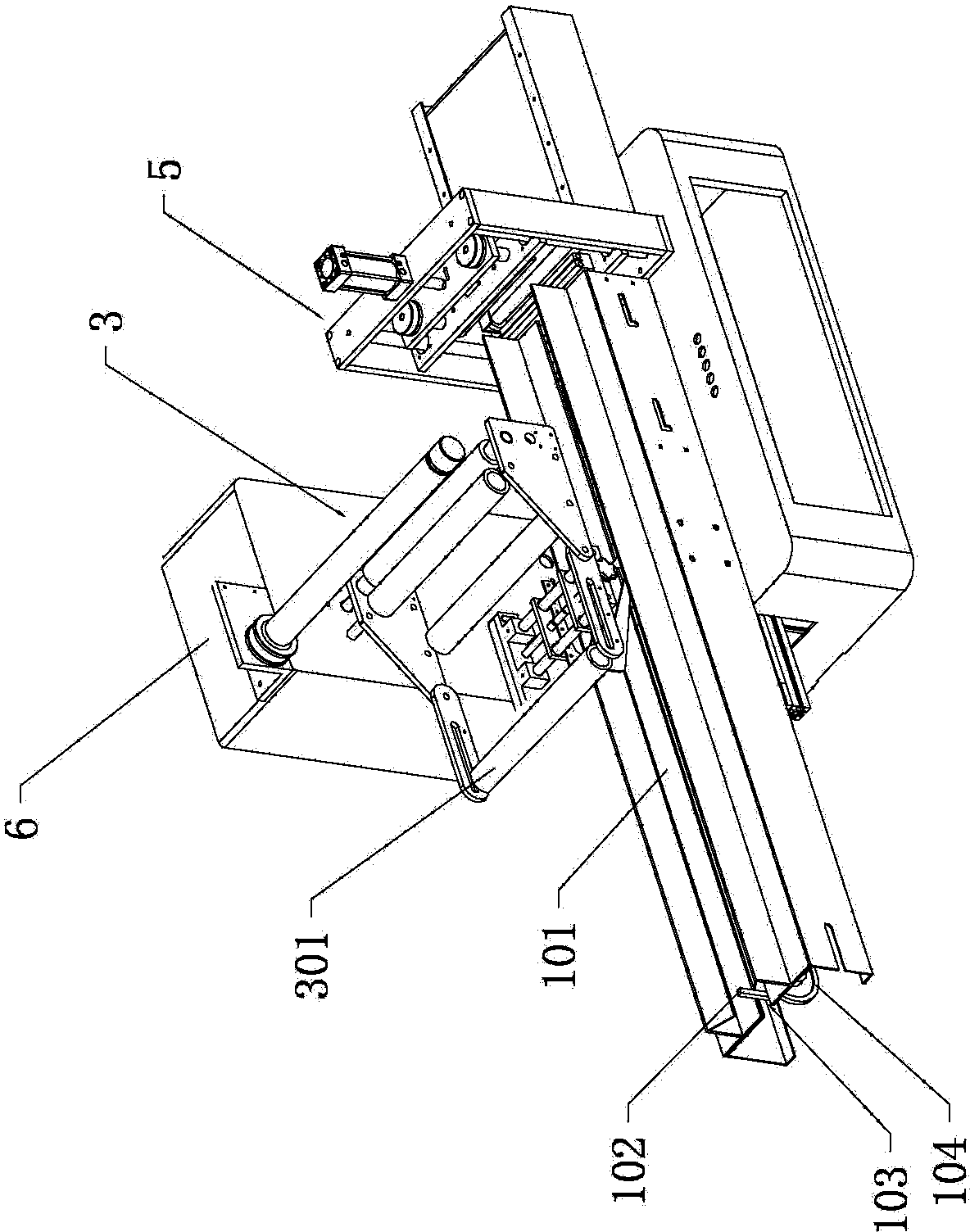
[0050] see figure 1 The transmission unit includes a transmission drive device, a transmission chain 104, a transmission path 101, a sensor, and a push piece 102 for pushing the material 9, the sensor is arranged on the transmission path 101, and the transmission path 101 is provided with a limited transmission groove 103, so The conveying chain 104 is located below the limiting conveying groove 103 , the pushing piece 102 is mounted on the conveying chain 104 , and the pushing piece 102 circulates around the conveying channel 101 . The transmission path is arranged in an inverted trapezoidal shape, which is beneficial for the material 9 to fall into the long groove 103 provided in the length direction of the transmission path 101. The length direction of the long groove is p...

Embodiment 2

[0071] The main technical solutions of this embodiment are basically the same as those of Embodiment 1, and the features not explained in this embodiment are explained in Embodiment 1, and will not be repeated here. The difference of this embodiment is that the middle seal transmission drive device and the transmission drive device are set as the same servo motor, and the servo motor is electrically connected to the controller. It should be noted that the middle seal transmission drive device and the transmission drive device can be servo motors In addition, it can also be an air cylinder, or the motor 105 of the transmission drive device of the transmission unit, and the motor 105 of the transmission drive device drives the transmission pressure wheel 401 and the transmission pulley 403 through the synchronous belt and the synchronous wheel. In order to make the moving speed of the conveying chain 104 of the conveying unit the same as the speed at which the film is driven by t...

Embodiment 3

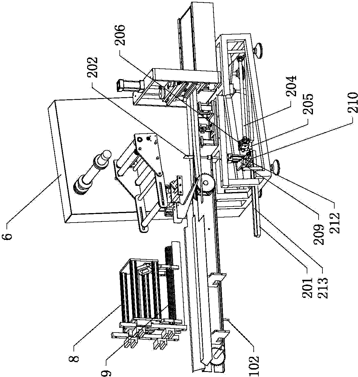
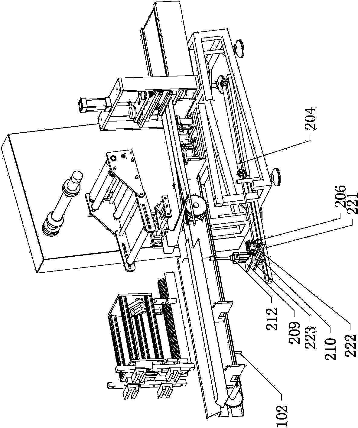
[0073] The main technical solutions of this embodiment are basically the same as those of Embodiment 1 or Embodiment 2, and the features not explained in this embodiment are explained in Embodiment 1 or Embodiment 2, and will not be repeated here. The difference between this embodiment and embodiment 1 is that, see Image 6 with Figure 7 , the abutment unit is provided with an abutment support frame 201, an abutment piece 202, an abutment piece forward pushing device, an abutment lifting device, a horizontal pushing device, a guide rail 213 (push guide piece) and a free slider 203 (sliding piece ). The abutting member 202 includes a connecting rod and an abutting plate, one end of the connecting rod is fixedly connected to the free slider 203, the other end of the connecting rod is fixedly connected to the abutting plate, and the free sliding block 203 is slidably sleeved on the guide rail 213 , the connecting rod is passed through the long slot 103 provided in the length d...


PUM


Abstract

The invention discloses a multifunctional automatic bagging device for a cup, a bowl and a cover. The multifunctional automatic bagging device comprises a leaning unit, a conveying unit, a film supporting and material conveying unit, a bagmaking heat sealing unit and a controller. Compared with the prior art, the multifunctional automatic bagging device has the advantages that by arrangement of the leaning unit for enabling a cup material such as the cover to be leaned against and preventing the cup material from being toppled over, the multifunctional automatic bagging device is wider in application range, can be used for automatically conveying and bagging a common water glass and can be also used for conveying, bagging and encapsulating of cup pieces (including a cup, a bowl, a box, a cover and the like) with diameters close to or greater than the heights and a plurality of rows of complete cup pieces of plastic small jelly containers (such as a peach-heart-shaped cup, a triangular cup, an elliptical cup and covers with other shapes) which have specific shapes and cannot roll away. According to the multifunctional automatic bagging device, automatic product conveying and bagging are realized, the automation degree is high, and the working efficiency is high; the demand for the quantity of workers is reduced, and labor cost is lowered; contact between a human body and a cup piece is avoided, so that the product is more sanitary and reliable.

Description

technical field [0001] The invention relates to the technical field of conveying and packaging equipment for cups, bowls and lids, in particular to a multi-kinetic automatic bagging device for cups, bowls and lids. Background technique [0002] At present, the packaging methods for cups, bowls, lids and other cups are mainly bagged manually and then sent to seal, which not only has low work efficiency and high labor costs, but also makes it difficult to meet the hygienic standards. However, there is currently no equipment that can be stacked and bagged for traditional cup making, especially for cups with a diameter close to or greater than the height (including cups, bowls, boxes and lids, etc.) and rows of small jelly plastics with special shapes that cannot be rolled. The conveying and bagging of the entire cup of the container (such as heart cup, triangular cup, oval cup and other shaped lids), because the diameter is close to or greater than the height of the cup (includ...

Claims


Application Information

Patent Timeline
Patent Type & Authority Applications(China)
IPC IPC(8): B65B35/44
CPCB65B35/40
Inventor 郑峰王昌佑
Owner GUANGDONG LONGXING PACKAGING IND
Why Eureka
Try Eureka