Full-grouting sleeve for connection of construction reinforcing steel bars

A construction steel bar and full grouting technology, which is applied to buildings, building components, building reinforcements, etc., can solve the problems of difficult control of engineering quality, poor positioning accuracy of steel bars and sleeves, and high labor intensity, so as to meet the quality requirements of building construction , Guaranteed positioning accuracy and low production cost

Inactive Publication Date: 2015-02-18
SHENYANG JIANZHU UNIVERSITY
View PDF4 Cites 15 Cited by
  • Summary
  • Abstract
  • Description
  • Claims
  • Application Information

AI Technical Summary

Problems solved by technology

[0006] The grouting sleeve is the core part of the steel bar connection, including a full grouting sleeve and a half-grouting sleeve. One end of the half-grouting sleeve is threaded to the steel bar, and the other end is connected to the steel bar by grouting. However, the half-grouting sleeve is used for the steel bar connection. The labor intensity is high, and it is not intuitive to judge whether the threaded connection between the steel bar and the sleeve is in place, it is easily affected by human factors, and the project quality is not easy to control
Although the existing full-grouting sleeve no longer uses threaded connection, when the steel bar and the sleeve are axially connected, precise axial control cannot be achieved, and there is no radial positioning function, and the positioning accuracy of the steel bar and the sleeve is extremely high. Poor, it is difficult to meet the quality requirements of building construction

Method used


Image

  • Full-grouting sleeve for connection of construction reinforcing steel bars
  • Full-grouting sleeve for connection of construction reinforcing steel bars
  • Full-grouting sleeve for connection of construction reinforcing steel bars

Examples


Embodiment Construction

[0024] The present invention will be further described in detail below in conjunction with the accompanying drawings and specific embodiments.

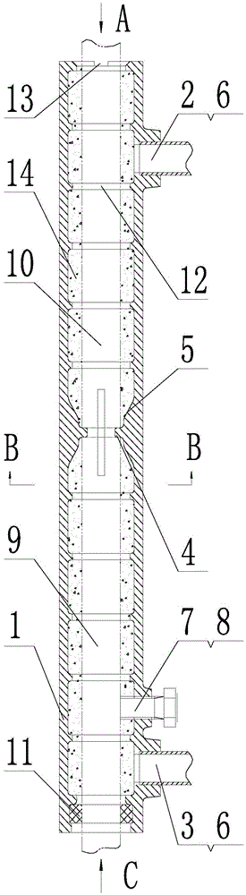
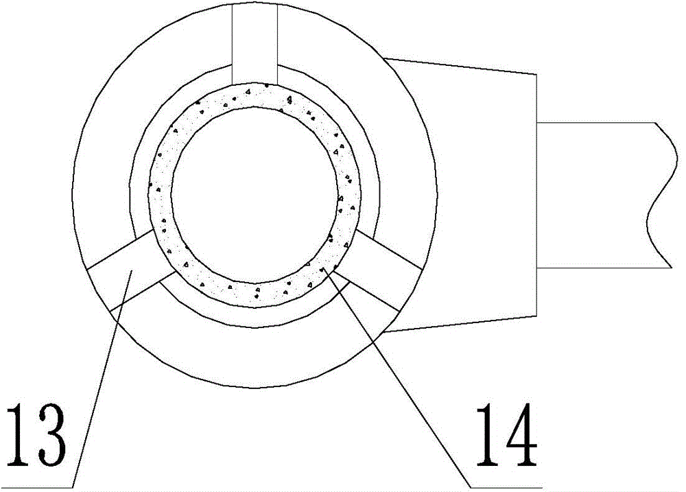
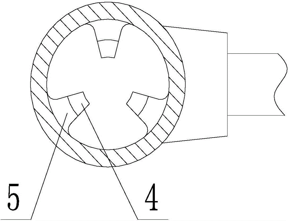
[0025] Such as figure 1 , 2 , Shown in 3 and 4, a kind of full grouting sleeve for building steel bar connection, comprises sleeve main body 1, first grouting port 2 and second grouting port 3, and one end of described sleeve main body 1 is the pouring-in-place end, The other end of the sleeve main body 1 is a prefabricated end, the first grouting port 2 is set on the cast-in-place end of the sleeve main body 1, and the second grouting port 3 is set on the prefabricated end of the sleeve main body 1, so Both the first grouting port 2 and the second grouting port 3 are connected with a grouting guide pipe 6, and on the inner wall of the middle part of the sleeve main body 1, a steel bar axial limit guide block 4 is arranged, and the steel bar axially A guide slope 5 is provided between the limit guide block 4 and the inner wall of th...


PUM


Abstract

The invention discloses a full-grouting sleeve for connection of construction reinforcing steel bars, and belongs to the technical field of building projects. A reinforcing steel bar axial-limiting guide stop dog is arranged on the inner wall in the middle of a sleeve main body; guide slopes are arranged between the stop dog and the inner wall of the sleeve main body; a positioning bolt is arranged on the sleeve main body at the prefabricated end; the reinforcing steel bar at the prefabricated end is axially and radially fixed through the positioning bolt; the sleeve main body is molded by one-step casting of spheroidal graphite cast iron, so that the production cost is low; the outer surface of the sleeve main body serves as a roughened surface, so as to ensure the anchoring force between the grouting sleeve and the concrete; a plurality of convex hooping ribs are arranged on the inner wall of the grouting sleeve; an identification gap is formed in the port face of the sleeve main body at the field poured end, so as to prevent the situation that the grouting sleeve is installed reversely; a seal ring is arranged inside the port of the sleeve main body at the prefabricated end. When the grouting sleeve disclosed by the invention is in axial butt joint with the reinforcing steel bar, the precise axial control can be automatically realized, and the radial positioning can be automatically realized, so as to ensure the positioning accuracy between the reinforcing steel bar and the grouting sleeve, and meet the requirements on building construction quality.

Description

technical field [0001] The invention belongs to the technical field of civil engineering, in particular to a full grouting sleeve for connecting building steel bars. Background technique [0002] At present, in my country's reinforced concrete building structures, most of the connection methods for building steel bars are traditional steel bar connection methods, namely binding, welding and threading. [0003] When the binding method and thread method are used, when the node gap of the component reinforcement is relatively small, it is difficult to use tools to bind it, so it is not suitable for the node reinforcement connection where the component reinforcement is relatively dense, and the construction quality is seriously affected by human factors, and the skeleton is easily deformed . [0004] When the welding method is used, it is also not suitable for the joint reinforcement connection with relatively dense component reinforcement, and the welding technology requiremen...

Claims


Application Information

Patent Timeline
Patent Type & Authority Applications(China)
IPC IPC(8): E04C5/16
Inventor 田野孙红张耀煌陈瑞三田璐
Owner SHENYANG JIANZHU UNIVERSITY
Why Eureka
Try Eureka