Pedal type inflating device

A pedal-operated and pedal-operated technology, which is applied to liquid variable volume machinery, machines/engines, mechanical equipment, etc., can solve the problems of high work intensity and inconvenient use, and achieve low work intensity and simple and convenient pumping. Effect

Inactive Publication Date: 2015-02-18
CHONGQING SHIXI TECH
View PDF0 Cites 2 Cited by
  • Summary
  • Abstract
  • Description
  • Claims
  • Application Information

AI Technical Summary

Problems solved by technology

[0004] The technical problem to be solved by the present invention is to provide a foot-operated pumping device with the advantages of convenient us

Method used


Image

  • Pedal type inflating device

Examples


Embodiment Construction

[0013] The present invention will be described in further detail below by means of specific embodiments:

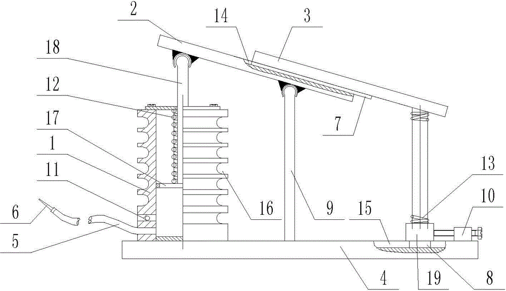
[0014] The reference signs in the accompanying drawings include: piston cylinder-1, first pedal-2, second pedal-3, base-4, hose-5, air needle-6, bump-7, Boss-8, support rod-9, positioning block-10, one-way air valve-11, return spring-12, support spring-13, groove-14, dovetail groove-15, spiral groove-16, piston-17 , Piston rod-18, sliding block-19.

[0015] The embodiment is basically as attached figure 1 Shown:

[0016] The pedal type pumping device is composed of a piston cylinder 1, a first pedal 2, a second pedal 3 and a base 4, the piston cylinder 1 is located on the base 4; the bottom of the piston cylinder 1 is provided with a hose 5, and the end of the hose 5 is There is an air needle 6 on the inside, a spiral groove 16 on the outer wall of the piston barrel 1, the hose 5 is stuck in the spiral groove 16, a piston 17 is arranged inside the piston barrel 1, a pi...


PUM


Abstract

The invention discloses a pedal type inflating device, which comprises a piston tube, a first pedal, a second pedal and a base, wherein the piston tube is positioned on the base, the lower end of the piston tube is provided with a one-way air pressure valve, the upper end of a piston rod is in ball hinging to the first pedal, a support rod is arranged on the base, the upper end of the support rod is in ball hinging to the first pedal, a groove is formed in the upper part of the first pedal, the bottom of the second pedal is provided with a convex block matched with the groove, a sliding groove is formed in the upper part of the base, a sliding block is arranged between the second pedal and the base, the bottom of the sliding block is provided with a lug boss matched with the sliding groove, a support spring is arranged between the second pedal and the sliding block, the support spring is respectively and fixedly connected with the sliding block and the second pedal, the end part of the base is provided with a positioning block, a regulating screw bolt is arranged on the positioning block, the regulating screw bolt and the positioning block are connected through screw threads, the positioning tube and the positioning block are respectively positioned at the two ends of the base, and the support rod is positioned in the middle part of the base.

Description

technical field [0001] The invention relates to a foot-operated pumping device. Background technique [0002] There are usually two ways to inflate the tires, one is the automatic inflating method and the other is the manual inflating method. The automatic inflating usually uses an air compressor to inflate the tires. The air compressor must have electricity to work, so the air The scope of use of the press is relatively limited. Compared with automatic pumping, manual pumping is more convenient to use and is not limited by electric energy. However, the existing manual inflating mode is usually a hand-pressed inflating device, and the hand-pressed inflating device is to make the piston rod drive the piston to extrude the gas by hand pressing the piston rod so as to inflate the tire. When using the hand-pressed pumping device, a person needs to bend over to pump the pump, which is inconvenient to use and has a high working intensity. [0003] This shows that the existing ha...

Claims


Application Information

Patent Timeline
IPC IPC(8): F04B33/00
Inventor 郭晓东
Owner CHONGQING SHIXI TECH
Why Eureka
Try Eureka