Novel tensioner

A tensioner, a new type of technology, applied in the field of auto parts, can solve the problems of increased vibration of the wheel train system, unguaranteed quality, cumbersome production process, etc., to achieve a long service life, reliable quality, and simple overall structure Effect

Inactive Publication Date: 2015-02-18
ALT JIANGSU IND
View PDF6 Cites 3 Cited by
  • Summary
  • Abstract
  • Description
  • Claims
  • Application Information

AI Technical Summary

Problems solved by technology

The structure of the tensioner is various, which generally includes a fixed structure and an elastic automatic adjustment structure. Automatic rebound controls the tension of the belt and chain, but most of the tensioners on the market have the following problems, the structure is complex, the production process is cumbersome, and after long-term use, yaw and tilt will occur, resulting in increased vibration of the gear train system and abnormal ring
The quality cannot be guaranteed, the service life is short, and the enterprise cost is high. Therefore, a new technical solution is urgently needed to solve this technical problem

Method used


Image

  • Novel tensioner
  • Novel tensioner
  • Novel tensioner

Examples


Embodiment 1

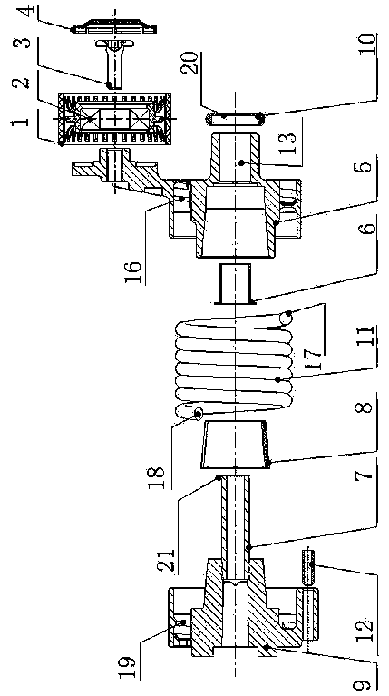
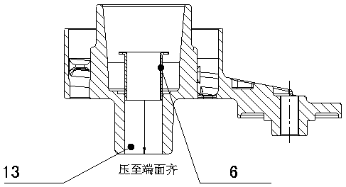
[0031] see figure 1 , a new type of tensioner, which includes: the tensioner includes a bottom housing 9, a spring 11 arranged in the housing, the tensioner also includes a tensioning arm 5, a central shaft 7, and the central shaft 7 is die-cast In the housing, which is integrated with the housing 9, the center of the tension arm 5 is provided with a center hole 13, and the center hole 13 is equipped with a self-lubricating bearing 6. The self-lubricating bearing 6 cooperates with the tension arm 5 to make the self-lubricating bearing 6 is pressed into the center hole of the tensioning arm 5, and the middle of the housing 9 and the tensioning arm 5 is provided with a nylon taper sleeve 8, and the tensioner also includes a pulley 1, a bearing 2, a bolt 3 and a dust cover 4 , the bolt 3 tightens the dust cover 4 and the bearing 2 on the tension arm 5, and the tightening torque of the bolt is 25±2.5N.m. When pressing in the self-lubricating bearing, the pressure head must be con...

Embodiment 2

[0033] see figure 1 , Figure 6 , as an improvement of the present invention, the spring is composed of a spring body 11 , an upper spring plane 17 and a lower spring plane 18 . Avoid the situation that the assembly is not in place during the assembly process. The rest of the structures and advantages are exactly the same as in Embodiment 1.

Embodiment 3

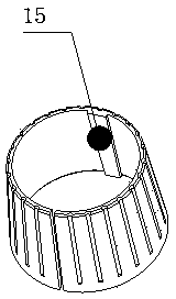
[0035] see figure 1 , Figure 5 , Figure 6 , Figure 7, as an improvement of the present invention, the bottom of the housing 9 is provided with a housing helical groove 19, the bottom of the tension arm 5 is provided with a tension arm helical groove 16, and the underspring plane 18 is connected to the bottom of the housing 9 The shell spiral groove 19, the spring upper plane 17 is connected to the spiral groove 16 of the tension arm 5, and the tension arm 5 and the shell 9 generate tension through the spring 11. The rest of the structures and advantages are exactly the same as in Embodiment 1.


PUM


Abstract

The invention relates to a novel tensioner. The tensioner is characterized by comprising a bottom casing, a spring arranged in the casing, a tensioning arm and a central rotating shaft, wherein the central rotating shaft is pressed and cast in the casing, and the central rotating shaft and the casing are formed into an integral whole; a center hole is formed in the center of the tensioning arm, a self-lubricating bearing is assembled in the center hole, and the self-lubricating bearing and the tensioning arm are matched to press the self-lubricating bearing into the center hole of the tensioning arm; a nylon taper sleeve is arranged between the casing and the tensioning arm; the tensioner also comprises a belt pulley, a bearing, a bolt and a dustproof cover, wherein the dustproof cover and the bearing are screwed on the tensioning arm by the bolt. The tensioner has the advantages of simple integral structure, convenience in operation and lower cost; the central rotating shaft is cast in the bottom of the casing in the manner of a mold insert, so that the central rotating shaft and the casing are reliably combined together and are formed into a whole, the firmness is better, and the service life is longer.

Description

technical field [0001] The invention relates to a tensioner, in particular to a novel tensioner, which belongs to the technical field of auto parts. Background technique [0002] The tensioner is a commonly used holding device on the belt and chain transmission system. Its main function is to keep the belt and chain with proper tension during the transmission process, so as to avoid the belt slipping, or to prevent the synchronous belt from jumping and detaching. phenomenon, or prevent the chain from loosening and falling off, and reduce the wear and tear of the sprocket and chain. The structure of the tensioner is various, which generally includes a fixed structure and an elastic automatic adjustment structure. Automatic rebound controls the tension of the belt and chain, but most of the tensioners on the market have the following problems, the structure is complex, the production process is cumbersome, and after long-term use, yaw and tilt will occur, resulting in increas...

Claims


Application Information

Patent Timeline
Patent Type & Authority Applications(China)
IPC IPC(8): F16H7/08
CPCF16H7/08
Inventor 王文焕
Owner ALT JIANGSU IND
Why Eureka
Try Eureka