
Electromagnetic ultrasonic thickness measurement method and device

An ultrasonic and thickness measurement technology, applied in the field of measurement, can solve problems such as the need to improve accuracy, and achieve the effect of highlighting substantive features, convenient implementation and improving accuracy

Inactive Publication Date: 2017-04-12
中电科信息产业有限公司 +1
View PDF8 Cites 0 Cited by
  • Summary
  • Abstract
  • Description
  • Claims
  • Application Information

AI Technical Summary

Problems solved by technology

[0004] In view of this, the purpose of the embodiments of the present invention is to provide an electromagnetic ultrasonic thickness measurement method and device to improve the accuracy of the ultrasonic thickness measurement method in the prior art.

Method used


Image

  • Electromagnetic ultrasonic thickness measurement method and device
  • Electromagnetic ultrasonic thickness measurement method and device
  • Electromagnetic ultrasonic thickness measurement method and device

Examples


Embodiment 1

[0042] It is found through research that if the thickness H is calculated directly from the time t from the burst wave to the detection of the first lower bottom echo cluster, that is, H=Vt / 2, where V is the transmission speed of the electromagnetic ultrasonic wave in the object to be detected, It can be found by looking up the manual or calculating by measuring. Due to the different environmental conditions of the burst wave, the internal defects that may exist in the object to be tested, etc., the thickness measurement results have a large deviation from the actual thickness. Calculation, namely H=V(t 2 -t 1 ) / 2, where t 2 -t 1 is the time difference between adjacent bottom-surface echo clusters (within the same trigger period).

[0043] The inventor found through research that although the calculation of the thickness based on the time difference of the adjacent bottom surface echo clusters can improve the calculation accuracy of the thickness of the object to be detect...

Embodiment 2

[0062] It is found through research that if the thickness H is calculated directly from the time t from the burst wave to the detection of the first lower bottom echo cluster, that is, H=Vt / 2, where V is the transmission speed of the electromagnetic ultrasonic wave in the object to be detected, It can be obtained by looking up the manual or through measurement and calculation. Due to the different environmental conditions of the burst wave and the possible internal defects of the object to be tested, the thickness measurement result has a large deviation from the actual thickness. In order to improve the thickness measurement accuracy, it is mainly based on phase The time difference of the echo cluster adjacent to the bottom surface is used to calculate the thickness, that is, H=V(t 2 -t 1 ) / 2, where t 2 -t 1 is the time difference between adjacent bottom-surface echo clusters (within the same trigger period).

[0063] The inventor found through research that although the c...


PUM


Abstract

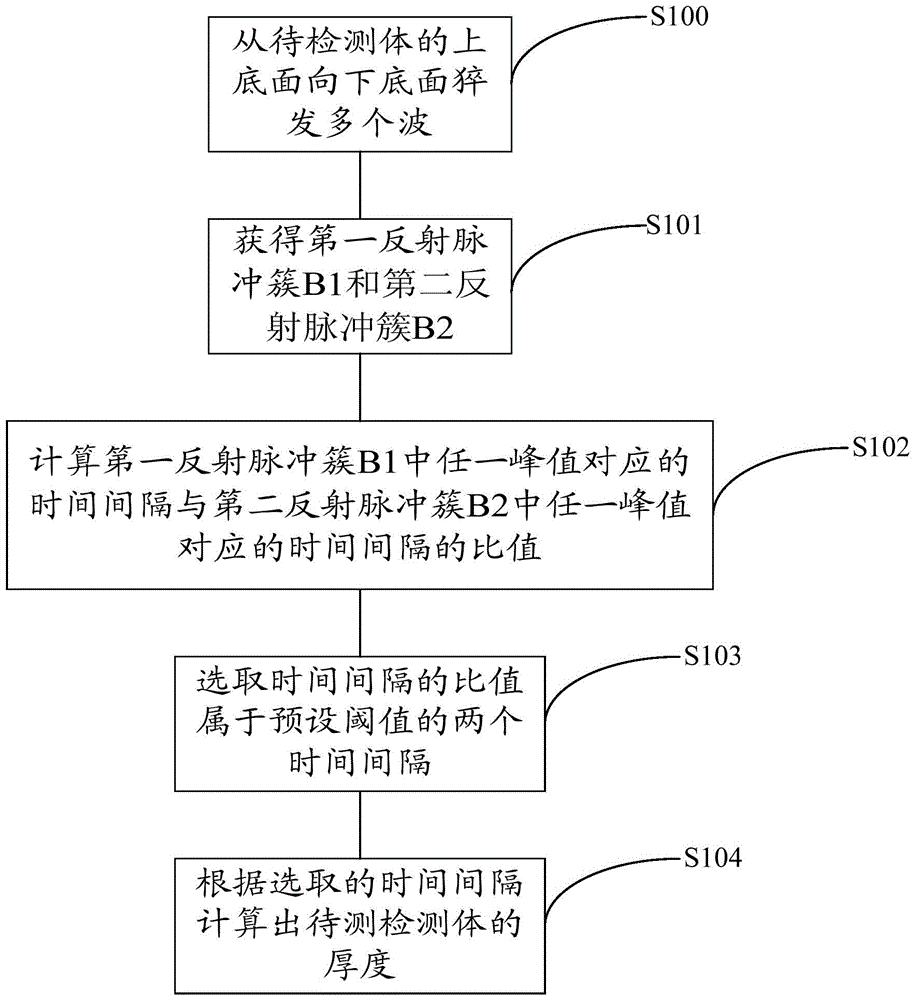
The embodiment of the present invention provides an electromagnetic ultrasonic thickness measurement method and device, which improves the problem that the accuracy of the existing ultrasonic thickness measurement method needs to be improved. The method includes: bursting a plurality of waves from the upper bottom surface of the object to be detected to the lower bottom surface; obtaining the first reflected pulse cluster B1 and the second reflected pulse cluster B2 of the burst multiple waves on the lower bottom surface of the object to be detected; the first reflected pulse cluster Both B1 and the second reflected pulse cluster B2 include a plurality of peaks, and each peak value in the first reflected pulse cluster B1 and the second reflected pulse cluster B2 corresponds to a time interval respectively; calculate any peak value in the first reflected pulse cluster B1 The ratio of the corresponding time interval to the time interval corresponding to any peak value in the second reflected pulse cluster B2, select two time intervals whose time interval ratio belongs to the preset threshold; calculate the thickness of the object to be tested according to the selected time interval. Using this method, the accuracy of ultrasonic thickness measurement can be significantly improved, and it is convenient to implement and easy to popularize and apply.

Description

technical field [0001] The invention relates to measurement technology, in particular to an electromagnetic ultrasonic thickness measurement method and device. Background technique [0002] Ultrasonic thickness measurement, that is, the use of ultrasonic waves for thickness measurement, the measurement principle is: when the ultrasonic pulse emitted by the probe passes through the object to be measured and reaches the interface of the material, the pulse is reflected back to the probe, and the time of ultrasonic propagation in the material is accurately measured to determine the thickness of the material. The thickness of the material can be measured, and all kinds of materials that can make the ultrasonic wave propagate inside it at a constant speed can be measured by this principle. [0003] In the prior art, the thickness calculation is mainly performed according to the time of the first detected bottom echo, or the thickness calculation is performed according to the time...

Claims


Application Information

Patent Timeline
Patent Type & Authority Patents(China)
IPC IPC(8): G01B17/02
CPCG01B17/02G01S15/08
Inventor 闫重强段凯钱宏亮王艳斌黄新超李赛霄李涛李占斌崔伟超
Owner 中电科信息产业有限公司
Learn More