A test device and test method for frost heave inside compacted soil
A testing device and soil compaction technology, which is applied in soil material testing, material inspection products, etc., can solve the problems of not being able to measure the amount of frost heave deformation inside the soil, soil freezing, etc., and achieve true and effective test results, convenient operation, and easy measurement. high precision effect
- Summary
- Abstract
- Description
- Claims
- Application Information
AI Technical Summary
Problems solved by technology
Method used
Image
Examples
specific Embodiment approach 1
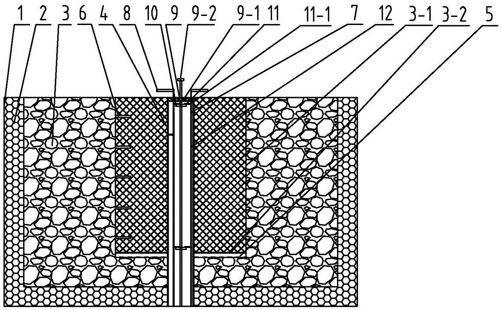
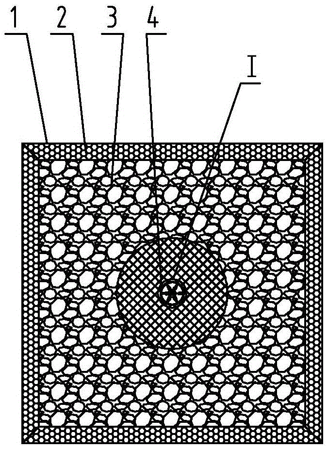
[0019] Specific implementation mode one: combine Figure 1 to Figure 3 To illustrate this embodiment, a test device for frost heaving inside compacted soil described in this embodiment includes a square groove 1, a foam board 2, an insulation layer 3, a plurality of probes 12, a sleeve 4 and a needle feeding mechanism. The cross-section of the groove 1 is square, and the foam board 2 is evenly arranged on the inner surface of the square groove 1, and the inner side of the foam board 2 is uniformly provided with an insulation layer 3, and the center of the insulation layer 3 is provided with a soil-like circular groove 3-1 The bottom surface of the soil sample circular groove 3-1 is provided with a semipermeable membrane 3-2, and the lower end of the semipermeable membrane 3-2 is provided with a water replenishing layer 5, and the inner wall of the soil sample circular groove 3-1 is uniform in the axial direction. A plurality of temperature sensors 6 are arranged, and the sleev...
specific Embodiment approach 2
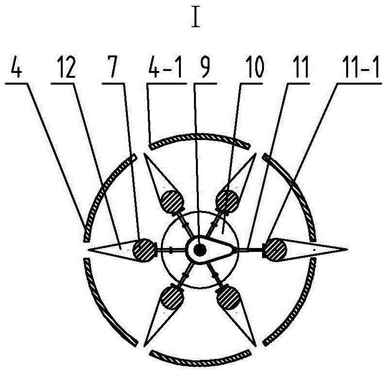
[0021] Specific implementation mode two: combination Figure 1 to Figure 3 Describe this embodiment. The needle feeding mechanism in this embodiment includes a rotary shaft 9, two inner groove cams 10 and a plurality of struts 11. The rotary shaft 9 is vertically arranged on the axis of the sleeve 4. The upper end of the rotary shaft 9 A positioning cover 9-1 is inserted, and the positioning cover 9-1 is rotationally connected with the rotary shaft 9. The positioning cover 9-1 cooperates with the top inner wall of the sleeve 4, and two ends of the rotary shaft 9 are respectively inserted with a Inner groove cam 10, two inner groove cams 10 are arranged in the same direction, and a plurality of struts 11 are evenly distributed on the outer circumference of each inner groove cam 10, and one end of each strut 11 matches the groove of inner groove cam 10 respectively , the other end of each pole 11 is respectively provided with a push plate 11-1, and each push plate 11-1 cooperate...
specific Embodiment approach 3
[0023] Specific implementation mode three: combination Figure 1 to Figure 3 To illustrate this embodiment, the length of each through slot 4 - 1 on the sleeve 4 in this embodiment is greater than the vertical distance between the top probe 12 and the bottom probe 12 . The undisclosed technical features in this embodiment are the same as those in the first embodiment.
[0024] With such a design, the probe 12 can be placed at any height, and at the same time, when the displacement of the probe 12 undergoes frost heave, the displacement of the probe 12 will not be affected due to the long length of the through groove 4-1. Make the measurement results more accurate.
PUM
| Property | Measurement | Unit |
|---|---|---|
| depth | aaaaa | aaaaa |
| diameter | aaaaa | aaaaa |
Abstract
Description
Claims
Application Information
 - R&D
- Intellectual Property
- Life Sciences
- Materials
- Tech Scout
- Unparalleled Data Quality
- Higher Quality Content
- 60% Fewer Hallucinations
Browse by: Latest US Patents, China's latest patents, Technical Efficacy Thesaurus, Application Domain, Technology Topic, Popular Technical Reports.
© 2025 PatSnap. All rights reserved.Legal|Privacy policy|Modern Slavery Act Transparency Statement|Sitemap|About US| Contact US: help@patsnap.com


