Supercharge Your Innovation With Domain-Expert AI Agents!

Light guide plate and method for machining same

A processing method and technology of light guide plate, applied in metal processing equipment, optics, light guide, etc., can solve problems such as interference

Inactive Publication Date: 2015-02-18
苏州向隆塑胶有限公司
View PDF5 Cites 9 Cited by
  • Summary
  • Abstract
  • Description
  • Claims
  • Application Information

AI Technical Summary

Problems solved by technology

However, in fact, when the microstructure patterns are laid out in the same way on both sides of the light guide plate, the arrangement of the microstructures is more regular, which is prone to interference.

Method used


Image

  • Light guide plate and method for machining same
  • Light guide plate and method for machining same
  • Light guide plate and method for machining same

Examples


Embodiment

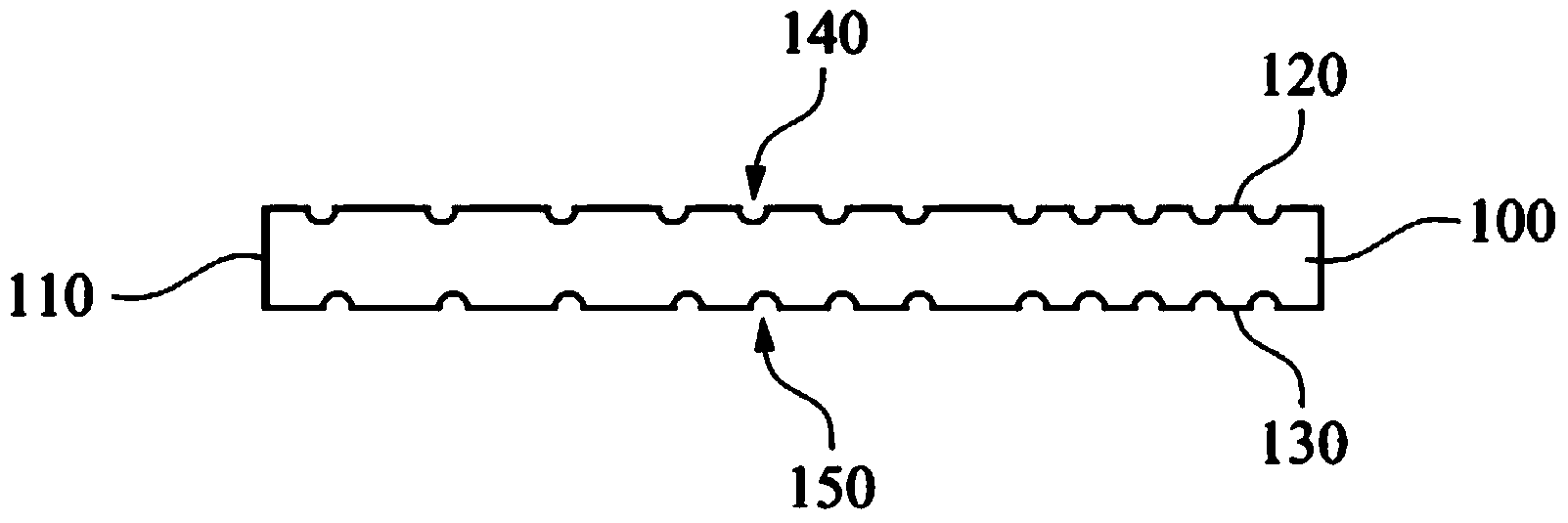
[0052] refer to figure 1 , figure 1 It is a side view of the light guide plate 100 in one embodiment of the present invention. This embodiment provides a light guide plate 100 , including a light incident side 110 , an upper surface 120 , a lower surface 130 , a first microstructure pattern 140 , and a second microstructure pattern 150 . The upper surface 120 is connected to the light incident side 110 . The lower surface 130 is connected to the light-incident side 110 and is disposed relative to the upper surface 120 . The first microstructure pattern 140 is disposed on the upper surface 120 . The second microstructure pattern 150 is disposed on the lower surface 130 .

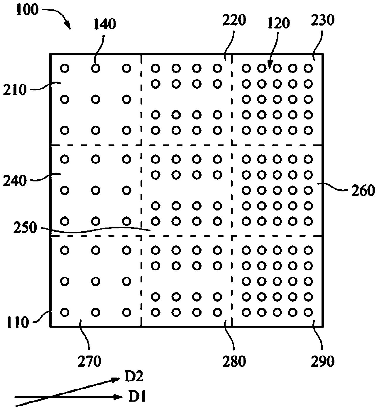
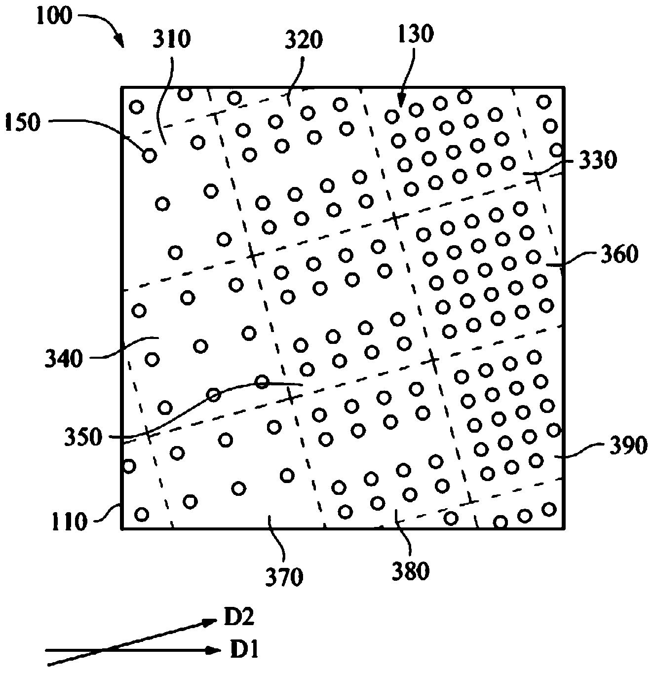
[0053] In one or more embodiments of the present invention, the first microstructure pattern 140 and the second microstructure pattern 150 can be a plurality of dot-shaped raised or depressed microstructures, and the first microstructure pattern 140 and the second microstructure pattern The light-trappin...


PUM


Abstract

The invention discloses a light guide plate and a method for machining the same. The light guide plate comprises an incident side surface, an upper surface, a lower surface, first microstructure patterns and second microstructure patterns. The upper surface is connected with the incident side surface. The lower surface is connected with the incident side surface and is opposite to the upper surface. The first microstructure patterns are arranged on the upper surface and are arranged along a first direction, the light extraction capacity of the first microstructure patterns is linearly progressively increased from the positions adjacent to the incident side surface to the positions far away from the incident side surface, the second microstructure patterns are arranged on the lower surface and are arranged along a second direction, an included angle between the first direction and the second direction ranges from 10 degrees to 50 degrees, and the light extraction capacity of the second microstructure patterns is linearly progressively increased from the positions adjacent to the incident side surface to the positions far away from the incident side surface. The light guide plate and the method have the advantages that the microstructure patterns on the double surfaces of the light guide plate are not distributed in identical directions and do not correspond to light sources over identical distances, and accordingly light ray interference due to the fact that microstructure patterns are regularly arranged on double surfaces of an existing light guide plate when the microstructure patterns of the existing light guide plate correspond to light sources over identical distances can be reduced.

Description

technical field [0001] The invention relates to a part of a backlight module, in particular to a light guide plate and a processing method thereof. Background technique [0002] The surface of the light guide plate is provided with a microstructure pattern (pattern) to destroy the total reflection of the light inside the plate, and then emit light. According to the different distances from the light source, each area of ​​the light guide plate requires different light-taking capabilities, and the density of microstructure patterns in each area is also different. This kind of microstructure pattern with different densities in each region involves many different processing methods and distribution methods. [0003] In order to increase the light emitting ability of the light guide plate, in the current light guide plate processing technology, not only the microstructure pattern is arranged on the light emitting surface of the light guide plate, but also the microstructure pat...

Claims


Application Information

Patent Timeline
Patent Type & Authority Applications(China)
IPC IPC(8): G02B6/00B23K26/36
CPCG02B6/0016G02B6/0036G02B6/0065
Inventor 吴俊潭叶钧皓
Owner 苏州向隆塑胶有限公司
Features
  • R&D
  • Intellectual Property
  • Life Sciences
  • Materials
  • Tech Scout
  • Unparalleled Data Quality
  • Higher Quality Content
  • 60% Fewer Hallucinations
Learn More