Automatic ground testing and relative camera pose estimation method in depth image

A technology of depth camera and depth image, which is applied in image enhancement, image analysis, image data processing, etc. It can solve problems such as lack of performance in complex environments, limited system application range, difficult height information, etc.

Active Publication Date: 2015-02-18
HUNAN SURE SECURE INTELLIGENCE CO LTD
View PDF2 Cites 28 Cited by
  • Summary
  • Abstract
  • Description
  • Claims
  • Application Information

AI Technical Summary

Problems solved by technology

Therefore, it can only be applied to some relatively simple scenarios, such as unreliable performance for complex environments
In addition, the exis

Method used


Image

  • Automatic ground testing and relative camera pose estimation method in depth image
  • Automatic ground testing and relative camera pose estimation method in depth image
  • Automatic ground testing and relative camera pose estimation method in depth image

Examples


Embodiment Construction

[0031] Explanation: In the formula describing the present invention, multi-dimensional vectors and matrices are represented in bold with regular fonts, such as A, depth, etc., while italics are not bold to indicate one-dimensional variables, such as x, y, z, u, v, etc.

[0032] The realization steps of the present invention are as follows:

[0033] The first step, calibrate the image:

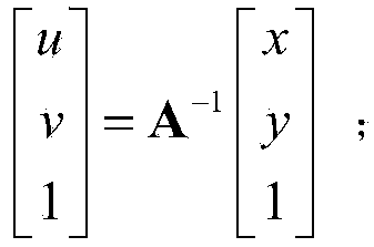
[0034] Assuming that the known internal parameter matrix of the depth camera is denoted as A, the internal parameter matrix can be offline through a classic calibration method such as Tsai's two-step method [1] and Zhang Zhengyou's planar method [2] Wait for it to be calculated. After obtaining the internal parameter matrix, convert the pixel coordinates of the depth image to radian coordinates, the following formula is wrong! Reference source not found. Shown:

[0035] u v ...


PUM


Abstract

The invention discloses an automatic ground testing and relative camera pose estimation method in a depth image. The method includes the steps: calibrating the depth image; computing a point cloud coordinate of each point in the depth image depth under a depth camera coordinate system per pixel; consistently extracting the ground based on random sampling; extracting ground normal vectors; computing the point cloud coordinates under a world coordinate system. Manual intervention is not required, and ground testing can be performed fully automatically; compared with an image color information based method, the method based on three-dimensional depth information has the advantages that ground testing is more accurate, and height of each pixel in a scene can be restored. In addition, by the method, current depth camera pose and scene height solving can be completed with only one image without depending on historical information.

Description

technical field [0001] The invention relates to an automatic ground detection method in a depth image and a camera relative pose estimation method. Background technique [0002] Ground detection has become a critical technology in the fields of robotics, autonomous driving, personal entertainment, and video surveillance. Most of the traditional image-based ground detection methods are based on the priori color information of the ground, the consistency of the color information and the strong edge to detect the ground, such as using the dark road surface of the highway and the white marking information on the side of the road. Its working method can only be applied to some relatively simple scenarios, and it does not have reliable performance for complex environments. In addition, in these application systems, it is often necessary to change the position of the depth camera at will, or the position of the depth camera will be affected by the system and change its position, s...

Claims


Application Information

Patent Timeline
IPC IPC(8): G06T7/00
CPCG06T7/80G06T2207/30244
Inventor 不公告发明人
Owner HUNAN SURE SECURE INTELLIGENCE CO LTD
Why Eureka
Try Eureka