
Power supporting integrated grounding electrode interconnection direct current magnetic bias restraining method

A technology of DC bias suppression and power support, applied in the field of power support combined with grounding pole interconnection and DC bias suppression, it can solve the problems of influence and no quantitative standard for adjustment of non-tested DC systems.

Active Publication Date: 2015-02-18
STATE GRID CORP OF CHINA +2
View PDF8 Cites 3 Cited by
  • Summary
  • Abstract
  • Description
  • Claims
  • Application Information

AI Technical Summary

Problems solved by technology

This method has the following problems: First, the effect of this method is affected by the distribution of earth resistivity between the tested DC system and the non-tested DC system, which has certain limitations; , the DC current into the ground will affect the AC system near the ground electrode of the DC system; the third is that this method does not give a clear quantitative standard for adjusting the non-tested DC system to a bipolar unbalanced operation mode

Method used


Image

  • Power supporting integrated grounding electrode interconnection direct current magnetic bias restraining method
  • Power supporting integrated grounding electrode interconnection direct current magnetic bias restraining method
  • Power supporting integrated grounding electrode interconnection direct current magnetic bias restraining method

Examples


Embodiment

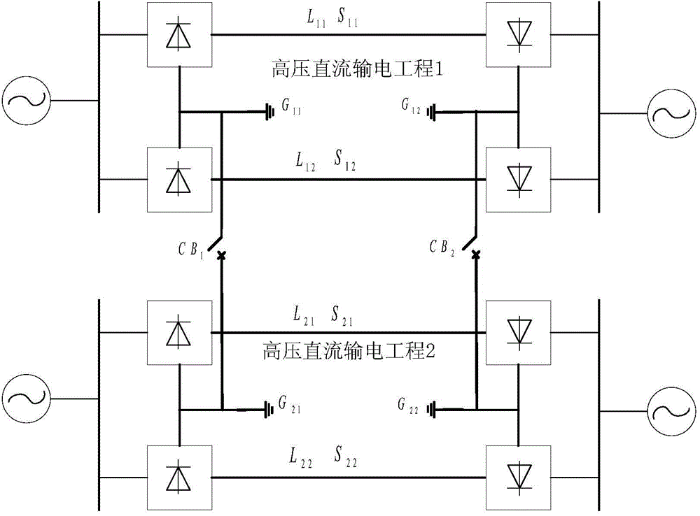
[0021] Using PSCAD / EMTDC electromagnetic transient simulation software to establish as figure 1 The simulation circuit shown. Among them, the parameter setting of DC project 1 refers to the Ge-Shang DC transmission project, and the parameter setting of DC project 2 refers to the Yi-Hua DC transmission project. The two DC transmission corridors are from Yichang, Hubei to Shanghai. Select 10 AC substations near the ground electrodes of the two DC transmission projects, namely: Anfusi substation (500kV), Gujiadian substation (220kV), Xiaoting substation (220kV), Baijiachong substation (220kV), Zhijiang substation (220kV), Guojiagang substation (220kV), Chaoyang substation (500kV), Changyang substation (220kV), station substation (220kV), Yangjiawan substation (220kV).

[0022] The Gezhouba ground electrode and the Yidu ground electrode are connected by a tie line. When the Gezhou-Shanghai DC transmission project is in the single-pole-earth operation mode, under the premise of en...


PUM


Abstract

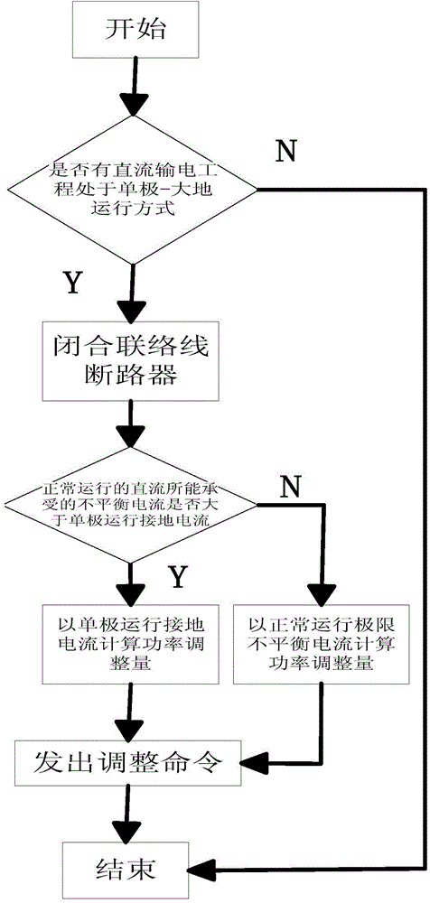
The invention provides a power supporting integrated grounding electrode interconnection direct current magnetic bias restraining method. The method is characterized by including the steps that firstly, whether a high-voltage direct current transmission project in two high-voltage direct current transmission projects is in a monopole-ground operation mode or not is judged, if not, a high-voltage direct current transmission power coordination type grounding electrode construction procedure is not started, otherwise, a second step is conducted; secondly, a call wire breaker CB1 and a call wire breaker CB2 are closed, a grounding electrode G11, a grounding electrode G12, a grounding electrode G21 and a grounding electrode G22 are connected in parallel, and the grounding electrode G21 and the grounding electrode G22 serve as shunt channels of the grounding electrode G11 and the grounding electrode G12; thirdly, unbalanced currents manufactured between two operation modes are compared, if the current not in the monopole-ground operation mode is large, the positive electrode transmission power and the negative electrode transmission power of the current not in the monopole-ground operation mode are adjusted according to the amplitude of the current in the monopole-ground operation mode, the unbalanced currents in the opposite direction are manufactured actively, and the currents shunted through call wires are counteracted, otherwise, adjustment is conducted according to the largest unbalanced current capable of being borne by the current not in the monopole-ground operation mode. By the adoption of the method, the large-amplitude direct current grounding currents can be well weakened and the safe and steady operation level of power grid equipment is increased.

Description

technical field [0001] The present invention relates to electric high-voltage direct current transmission technology, in particular how to quickly transfer and balance the large direct current into the ground when a high-voltage direct current transmission project is in the unipolar-ground operation mode, so as to reduce the impact of the direct current into the ground on the ground The power support of the adverse effect of the neutral grounding transformer around the pole is combined with the DC bias suppression method of the ground pole interconnection. Background technique [0002] When the high-voltage direct current transmission project is in single-pole-earth operation, a relatively large magnitude of direct current into the ground will invade the neutral point grounding transformer around the grounding pole, causing the hysteresis curve of the transformer core to deviate from the normal operating point, causing the DC bias phenomenon of the transformer. It affects th...

Claims


Application Information

Patent Timeline
IPC IPC(8): H02H9/02H02J3/36
CPCY02E60/60
Inventor 全江涛谢志成童歆林湘宁阮羚李正天张露丁苏阳
Owner STATE GRID CORP OF CHINA
Learn More