A kind of AP, data sending method and data receiving method

A technology for sending to and access points, which is applied in the field of network communication and can solve problems such as high complexity of deployment methods

Active Publication Date: 2018-05-22
RUIJIE NETWORKS CO LTD
View PDF6 Cites 0 Cited by
  • Summary
  • Abstract
  • Description
  • Claims
  • Application Information

AI Technical Summary

Problems solved by technology

[0005] The embodiment of the present invention provides an AP, a data sending method, and a data receiving method to solve the problem of high complexity of AP deployment methods provided in the prior art when different networks need to be used

Method used


Image

  • A kind of AP, data sending method and data receiving method
  • A kind of AP, data sending method and data receiving method
  • A kind of AP, data sending method and data receiving method

Examples


Embodiment 1

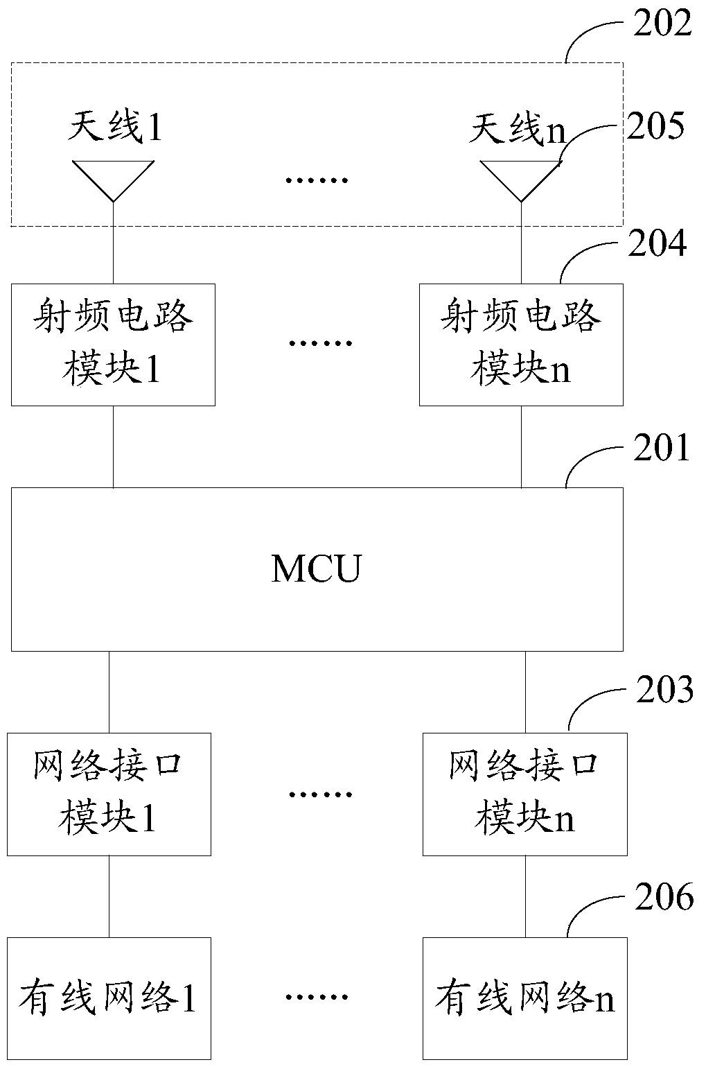
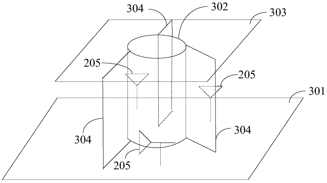
[0057] In Embodiment 1 of the present invention, an AP is provided based on figure 2 The shown AP provides the structure of the antenna array 202. The antenna array 202 provided in Embodiment 1 specifically includes: an antenna bottom plate 301, a cylindrical partition 302, and an upper bottom plate 303;

[0058] Wherein, the antenna bottom plate 301 is connected to the cylindrical partition 302 as the lower bottom surface of the cylindrical partition 302;

[0059] The upper bottom plate 303 is connected to the cylindrical partition 302 as the upper bottom surface of the cylindrical partition 302;

[0060] The antenna 205 is arranged in isolation from each other in a space formed by the antenna bottom plate 301 , the cylindrical partition 302 , and the upper bottom plate 303 along the circumferential direction of the cylindrical partition 302 .

[0061] Furthermore, the embodiment of the present invention also provides an implementation manner in which the antennas 205 are i...

Embodiment 2

[0075] In Embodiment 2 of the present invention, an AP is provided. The difference from the AP provided in Embodiment 1 is that the AP includes two network interface modules, such as Image 6 As shown, the network interface module 1 and the network interface module 2 are connected to the wired network 1 and the wired network 2 respectively, the network interface module 1 corresponds to the radio frequency circuit module 1, the network interface module 2 corresponds to the radio frequency circuit module 2, and the radio frequency circuit module 1 and the radio frequency circuit module 2 have respective corresponding antennas 205 in the antenna array. Moreover, the embodiment in which the antennas 205 are isolated from each other in the space where they are deployed does not pass through the vertical partition.

[0076] Figure 7A schematic diagram of the structure of the antenna array 202 in the AP provided for the embodiment of the present invention, as shown in Figure 7 As...

Embodiment 3

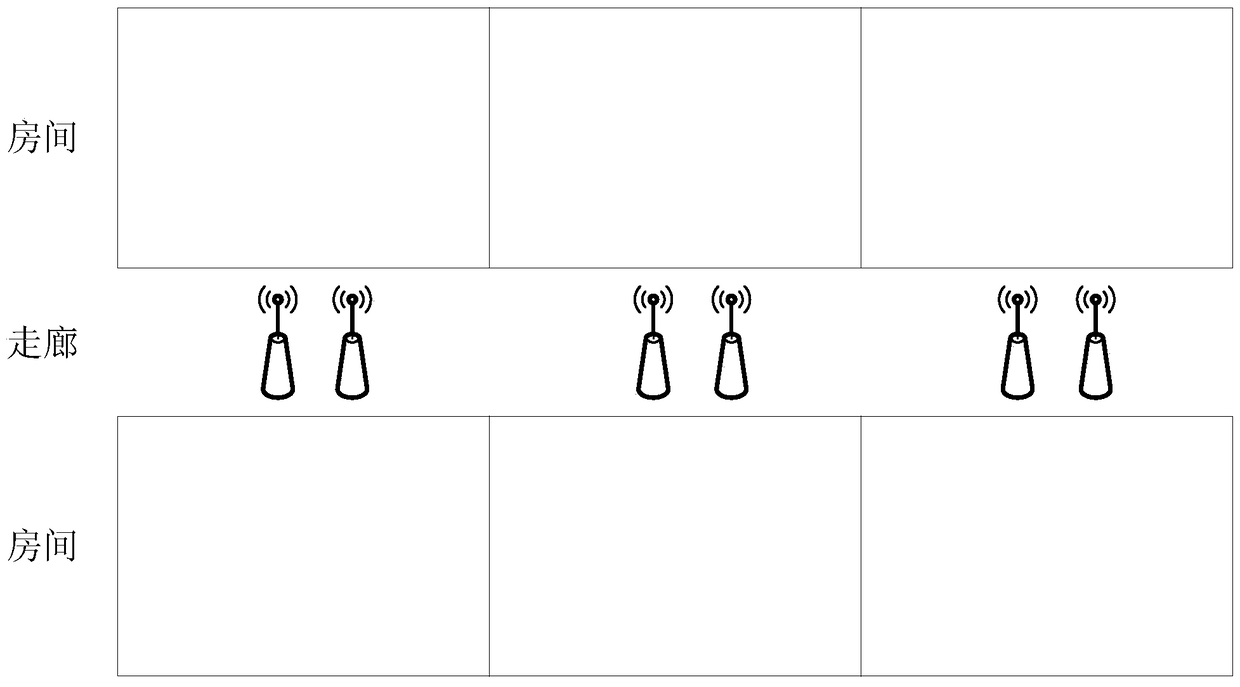
[0081] In the AP provided in Embodiment 1 and Embodiment 2 of the present invention, the antennas in the AP are isolated from each other, and the signals transmitted or received by different antennas in the AP will not interfere with each other. However, when multiple APs are deployed adjacent to each other, the may interfere with each other. In Embodiment 3 of the present invention, an AP is provided. Multiple antenna groups are set in the AP, and each AP uses an antenna group different from the antenna group used by the AP deployed adjacent to itself, so as to Ensure that adjacent APs do not interfere with each other;

[0082] Take the AP including two network interface modules as an example, such as Figure 9 As shown, the antenna array 202 in the AP provided by the embodiment of the present invention includes two antenna groups 901, and the antennas in each antenna group 901 correspond to different radio frequency circuit modules 204;

[0083] The antennas in the two ante...


PUM


Abstract

An embodiment of the present invention provides an AP, a data sending method, and a data receiving method, including: MCU, antenna array, at least two network interface modules, and a radio frequency circuit module; the network interface module is used to receive wired network signals and convert them into digital signals Send to the MCU; receive the digital signal sent by the MCU and convert it into a wired network signal and send it to the wired network; the MCU is used to receive the digital signal sent by the network interface module and send it to the RF circuit module; receive the digital signal sent by the RF circuit module and send it to the Network interface module; the radio frequency circuit module is used to receive the radio frequency signal sent by the antenna and demodulate it into a digital signal and send it to the MCU; receive the digital signal sent by the MCU and modulate it into a radio frequency signal and send it to the antenna; the antenna is used to receive the radio frequency signal and send it to the radio frequency The circuit module; receives the radio frequency signal sent by the radio frequency circuit module and sends it out. Reduce the complexity of AP deployment. Involved in the field of network communication.

Description

technical field [0001] The present invention relates to the technical field of network communication, in particular to an AP, a data sending method and a data receiving method. Background technique [0002] With the rapid development of the Internet and the continuous improvement of informatization, the importance of ensuring information security has become increasingly prominent. Many companies, governments, schools, etc. need to separate the extranet from the private network to ensure the prevention of large amounts of information leakage and hacker attacks . [0003] The structure of a traditional AP usually has only one network interface, which is connected to the switch and server through the network interface, and the users who access through the AP must transmit data through the network interface. If an enterprise needs two kinds of wireless networks (for example: one is an internal private network and the other is an external Internet), you can install two APs at on...

Claims


Application Information

Patent Timeline
Patent Type & Authority Patents(China)
IPC IPC(8): H04L29/04H04W16/18H04W24/00H04L69/14
CPCH04W16/18H04W24/00
Inventor 黄如希
Owner RUIJIE NETWORKS CO LTD
Why Eureka
Try Eureka