
Flue gas collection device with multiple rows of staggered diversion tube bundles and triangular expansion cover

A technology of flue gas collection and guide pipe, which is applied in the direction of dust removal, cleaning methods and utensils, and separation of dispersed particles. It can solve the problems of increased dust content and high speed in the exhaust hood, and achieve good dust suppression and dust reduction. The effect of changing the characteristics of the flow field and uniform velocity distribution of the cross-flow section

Active Publication Date: 2016-02-10
XI'AN UNIVERSITY OF ARCHITECTURE AND TECHNOLOGY
View PDF5 Cites 0 Cited by
  • Summary
  • Abstract
  • Description
  • Claims
  • Application Information

AI Technical Summary

Problems solved by technology

2. Due to the high momentum when the material collides with the surface of the belt conveyor, part of the momentum is lost after the collision, but part of the momentum is still not consumed. The small particle material with this momentum will increase with the amount of air entrained in the material during the collision. Released and migrated into the air to generate dust
Their improvement can play the role of dust reduction and dust collection to a certain extent, but the velocity on the section where the air outlet is located is relatively high, the static pressure is small, and the flow of dusty airflow is mainly concentrated on the surface of the belt conveyor. When the airflow velocity Enough to carry small-sized materials off the surface of the conveyor belt, the dust content in the exhaust hood will increase accordingly

Method used


Image

  • Flue gas collection device with multiple rows of staggered diversion tube bundles and triangular expansion cover
  • Flue gas collection device with multiple rows of staggered diversion tube bundles and triangular expansion cover
  • Flue gas collection device with multiple rows of staggered diversion tube bundles and triangular expansion cover

Examples


Embodiment 1

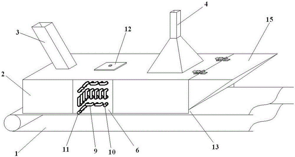
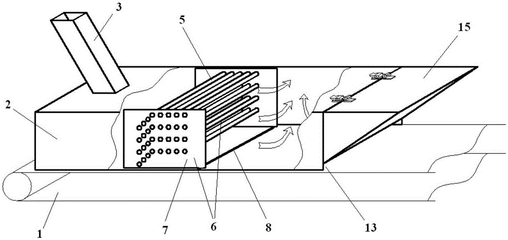
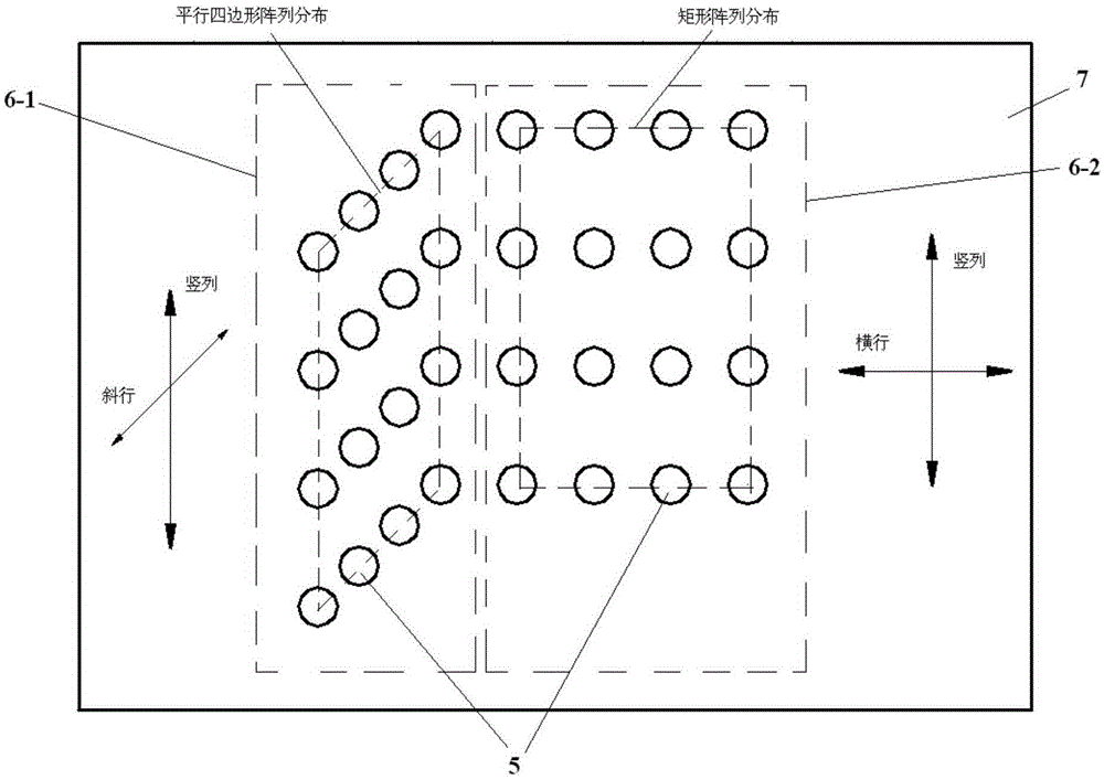
[0071] In order to overcome the technical deficiencies in Comparative Document 1, such as Figure 1 to Figure 5 As shown, the present embodiment provides a flue gas collection device, including an exhaust hood 2 arranged above the conveyor belt 1, the exhaust hood 2 is provided with a feeding port 3 and a draft port 4, and the feeding port 3 and the exhaust port The interior of the exhaust hood 2 between the ports 4 is equipped with a detachable multi-row staggered diversion tube bundle 6 composed of diversion tubes 5, and the diversion tubes 5 are perpendicular to the running direction of the material on the conveyor belt 1;

[0072] The cross-sectional layout of the multi-row staggered diversion tube bundle 6 is divided into two areas, the area near the discharge port 3 is the stop guide area 6-1, and the area near the air outlet 4 is the post-settlement and flow stabilization area 6-2;

[0073] The stop guide front area 6-1 is used for multiple collisions and frictions to ...

Embodiment 2

[0090] This embodiment provides a flue gas collection device, the other structures are the same as in Embodiment 1, the difference is that the guide tube 5 is a hollow tube, and the end of the guide tube 5 protruding from the tube plate is connected through an adapter 9 , an inlet 10 and an outlet 11 are reserved, and the entire multi-row staggered guide tube bundle 6 forms a connected pipeline, and heating agent or refrigerant can be passed into the guide tube 5 to realize the internal ventilation of the exhaust hood 2 Heating or cooling, such as hot water or cold water, can better collect flue gas for some materials with special temperature requirements. The equipment can not only reduce dust and suppress dust, but also play a role in cooling, recovering waste heat and reusing it, which can meet the requirements of energy saving.

Embodiment 3

[0092] This embodiment provides a smoke collection device, other structures are the same as in Embodiment 1, the difference is that the end surface of the exhaust hood 2 close to the feeding opening 3 is closed, and the end surface of the exhaust hood 2 close to the air outlet 4 is also closed But this end face is provided with discharge opening 13 near the side of conveyer belt 1, and the exhaust hood 2 closed end surface of the top of discharge opening 13 is processed with expansion opening 14, and the sealing cover on expansion opening 14 is closed with triangular expansion cover 15, triangular expansion cover 15. The right-angled surface of the expansion cover 15 in contact with the expansion opening 14 is open, and the other right-angled surface of the triangular expansion cover 15 is flush with the top surface of the exhaust hood 2 . The included angle between the triangular expansion cover 15 and the top surface of the exhaust hood 2, which is flush with the right-angled...


PUM

PropertyMeasurementUnit
angleaaaaaaaaaa
diameteraaaaaaaaaa
diameteraaaaaaaaaa

Abstract

The invention provides a smoke collecting device with a plurality of rows of staggered flow guide tube bundles and a triangular capacity expanding cover. The smoke collecting device comprises an exhaust hood arranged above a transmission belt, wherein a blanking hole and an air extracting hole are formed in the exhaust hood; a plurality of rows of detachable staggered flow guide tube bundles formed by flow guide tubes are mounted in the exhaust hood between the blanking hole and an air outlet; the flow guide tubes are perpendicular to the material running direction of the transmission belt; section layout of the plurality of rows of staggered flow guide tube bundles is divided into two areas; the area close to one side of the blanking hole is a front stop guide front; the area close to one side of the air outlet is a rear settling and flow-stabilizing area; the triangular capacity expanding cover is also arranged at the end of the exhaust hood. By virtue of the device, the dust can be reduced by horizontally washing the plurality of rows of staggered flow guide tube bundles; the smoke flow can be effectively guided; the capacity is expanded; the change of the dust amount generated instantaneously can be adjusted. Meanwhile, the uniformity of a flow field can be improved by coupling effect of the tube bundles and the capacity expanding cover.

Description

technical field [0001] The invention belongs to the field of dust suppression and dust reduction for transported materials, and relates to a tube bundle structure for dust reduction and dust collection, uniform flow field, and prevention of dust escape, in particular to a multi-row staggered guide tube bundle for preventing dust escape and a transient A flue gas collection device with a triangular expansion cover structure with a flue gas buffer function. Background technique [0002] Material conveying is widely used in conveying processes with different specifications and distances in the industrial and agricultural fields. There are often transfer stations during transportation, and materials usually fall from high-level belt conveyors or other feeding devices to low-level belt conveyors through chutes. The falling materials are easy to generate dust when they fall on the belt. The main reasons for the dust are as follows: 1. The materials falling at high speed induce th...

Claims


Application Information

Patent Timeline
Patent Type & Authority Patents(China)
IPC IPC(8): B01D45/08B01D45/02B08B15/02
CPCB01D45/02B01D45/08B08B15/02B08B15/04B08B2215/00
Inventor 王怡任晓芬樊航段梦婕曹莹雪杨洋黄艳秋
Owner XI'AN UNIVERSITY OF ARCHITECTURE AND TECHNOLOGY
Learn More