Composite seat energy absorption structure for vehicles

An energy-absorbing structure and seat technology, which is applied to vehicle seats, special positions of vehicles, and vehicle components, etc., can solve problems such as easy sprains of the neck

Inactive Publication Date: 2015-02-25
江苏悦达延锋汽车部件有限公司
View PDF9 Cites 1 Cited by
  • Summary
  • Abstract
  • Description
  • Claims
  • Application Information

AI Technical Summary

Problems solved by technology

[0004] The purpose of the present invention is to solve the problem that the occupant's neck in the rear-end vehicle

Method used


Image

  • Composite seat energy absorption structure for vehicles

Examples


Example Embodiment

[0012] The present invention is described in further detail now in conjunction with accompanying drawing. These drawings are all simplified schematic diagrams, which only illustrate the basic structure of the present invention in a schematic manner, so they only show the configurations related to the present invention.

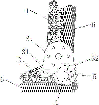
[0013] like figure 1 As shown, a seat composite energy-absorbing structure for automobiles of the present invention includes a seat back 1, a seat cushion 2 and a buffer energy-absorbing structure, and the bottom ends on both sides of the seat back 1 are respectively installed through connecting plates 3 At the rear ends on both sides of the seat cushion 2, the lower side of the connecting plate 3 is provided with a front mounting foot 31 and a rear mounting foot 32, and the front mounting foot 31 is hinged on the seat cushion 3. The C-shaped buffer plate device between the rear mounting feet 32 ​​and the seat cushion 3 and the cushioning energy-absorbing mat...


PUM

PropertyMeasurementUnit
Densityaaaaaaaaaa
Densityaaaaaaaaaa
Densityaaaaaaaaaa

Abstract

The invention relates to a composite seat energy absorption structure for vehicles. The composite seat energy absorption structure comprises a seat back, a seat cushion and a buffer and energy absorption structure. The bottom ends of two sides of the seat back are mounted to the rear ends on two sides of the seat cushion respectively through connecting plates, a front mounting support and a rear mounting support are arranged on the lower sides of each connecting plate, and each front mounting support is hinged to the seat cushion. The composite seat energy absorption structure is characterized in that the buffer and energy absorption structure comprises C-shaped buffer plate structures and buffer and energy absorption material layers, wherein each C-shaped buffer plate structure is mounted between each rear mounting support and the seat cushion, and the buffer and energy absorption material layers are arranged on the back of the seat back and the bottom of the seat cushion. Each C-shaped buffer plate structure comprises a C-shaped buffer plate and a limiting plate, one endpoint of each C-shaped buffer plate is hinged to the the rear mounting support of the corresponding connecting plate while the other endpoint is hinged to the seat cushion, a positioning hole and a limiting slot are formed in each limiting plate, one endpoint of each C-shaped buffer plate is hinged to the positioning hole of the corresponding limiting pate while the other endpoint is moveably mounted in the corresponding limiting slot, the positioning holes are round holes, the limiting slots are oblong holes, and the circle center of each positioning hole is located on the center line of the corresponding limiting slot.

Description

technical field [0001] The invention relates to a seat composite energy-absorbing structure for automobiles. technical background [0002] The safety of passenger vehicles has attracted more and more attention from designers and users. my country also has a complete crash star rating system and strong inspection regulations. When the rear of the car is hit by a rear-end collision, since the seat cannot move, the back of the occupant is close to the back of the seat, and the pressure on the back of the seat is more than 5 times that of the normal situation, and the support point of the head is small. Inertial leaning back can easily sprain the neck. Therefore, a car seat needs a cushioning energy-absorbing structure to reduce the instantaneous impact on the occupant during a rear-end collision and protect the occupant. [0003] On February 24, 2010, the Chinese Patent Office announced the CN201410899Y patent, which is called the energy-absorbing car seat headrest during rea...

Claims


Application Information

Patent Timeline
IPC IPC(8): B60N2/42
CPCB60N2/4249
Inventor 洪雷
Owner 江苏悦达延锋汽车部件有限公司
Why Eureka
Try Eureka