
Wiper motor free of lateral swing

A wiper and oscillating technology, applied in the field of wiper motors, can solve the problems of increased friction between the worm gear and the worm shaft, increased wear, shortened service life of the motor, etc. The effect of reducing the cost of parts and improving the processing efficiency

Inactive Publication Date: 2015-02-25
ZHEJIANG SHENGHUABO ELECTRICAL APPLIANCE
View PDF4 Cites 1 Cited by
  • Summary
  • Abstract
  • Description
  • Claims
  • Application Information

AI Technical Summary

Problems solved by technology

Because the armature shaft is limited by its structure and size, it is generally produced with slender round steel with an aspect ratio greater than 12; if the deviation of the processing hole used to connect the worm shaft support is too large, it will affect the assembly quality of the motor, which will lead to The worm shaft works in the wiper motor, which is prone to axial movement and radial runout, which intensifies the friction between the worm gear and the worm shaft, aggravates the wear and increases the noise, thus shortening the service life of the motor
[0003] In addition, it is well known that in the prior art, in order to eliminate the radial runout and axial runout of the worm shaft, for example: as disclosed in ZL 20092011337.7, the reduction base is matched with the worm gear in the motor base A similar worm gear device is added to the other end of the worm shaft to eliminate the axial runout and radial runout generated during its operation. This structure not only increases the volume and cost of the gearbox, but also increases the operation of the newly added worm gear device. The working power of the wiper motor is increased, and the noise when the wiper motor is running is also increased.

Method used


Image

  • Wiper motor free of lateral swing
  • Wiper motor free of lateral swing
  • Wiper motor free of lateral swing

Examples


Embodiment Construction

[0011] The present invention will be described in further detail below in conjunction with the accompanying drawings and embodiments.

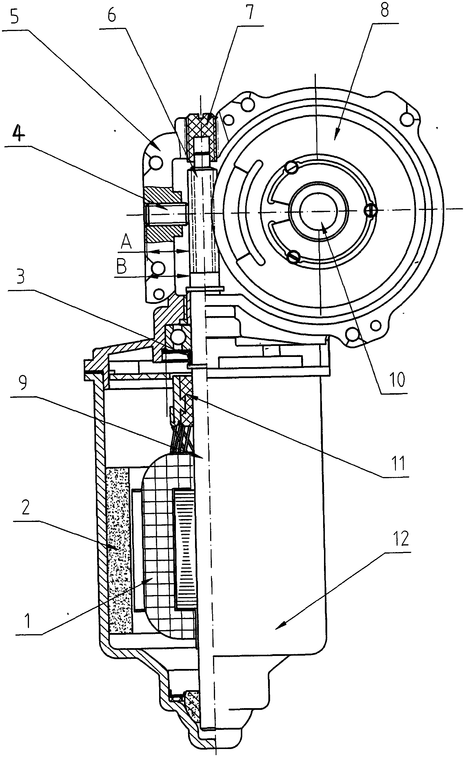
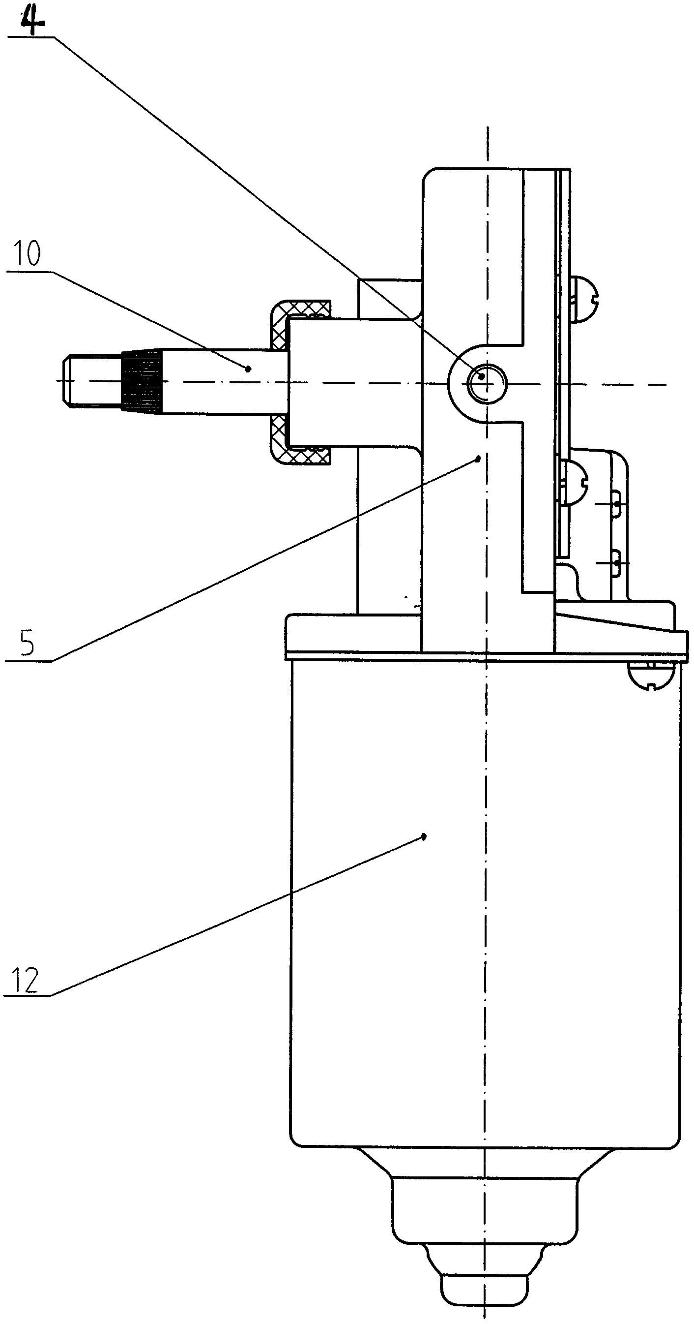
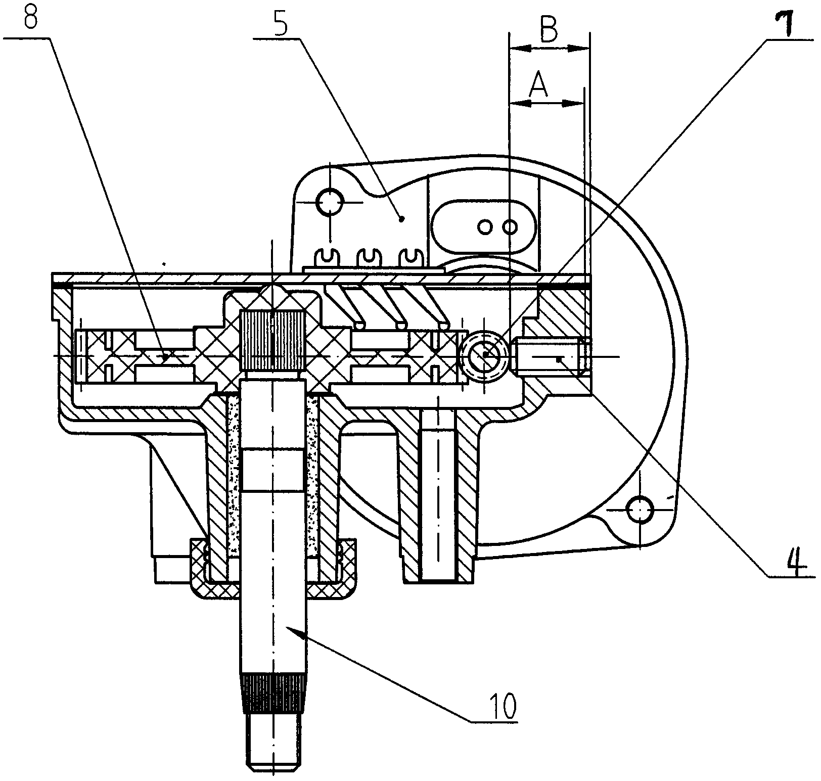
[0012] refer to Figure 1 to Figure 4 It can be known that the present invention does not have a lateral swing type wiper motor, which includes a motor body and a reduction box assembly. The reduction box 5 of the reduction box assembly is equipped with (a pair of) worm gears 8 and worm shafts 6 that mesh with each other. The worm shaft 6 is connected to the armature shaft 9 of the motor body (i.e., the output shaft of the motor) (integrated), the worm wheel 8 is connected to the worm shaft 10, and at the opposite position (longitudinal) where the worm wheel 8 and the worm shaft 6 mesh A radial adjustment element 4 (a radial adjustment stop screw) is installed on the worm shaft 6, and an axial adjustment element 7 (an axial adjustment screw) is installed on the outer end of the worm shaft 6; The adjustment element 4 (radial adjustment block s...


PUM


Abstract

The invention relates to a wiper motor free of lateral swing. The wiper motor comprises a motor body and a reduction gearbox assembly. A worm wheel (8) and a worm shaft (6) meshed with the worm wheel (8) are arranged in a reduction gearbox (5) of the reduction gearbox assembly, the worm shaft is connected with an armature shaft (9) of the motor body, and the worm wheel is connected with a worm wheel shaft (10). A radial adjustment element (4) is arranged at the position, back on to the meshing position of the worm wheel and the worm shaft, of the worm shaft, an axial adjustment element (7) is arranged at the outer end of the worm shaft, and the radial adjustment element and the axial adjustment element are installed on the reduction gearbox of the reduction gearbox assembly. Radial swing and axial play of the worm shaft can be effectively eliminated, machining is convenient, installation quality can be guaranteed, running noise can be lowered, and the service life of the wiper motor can be prolonged.

Description

technical field [0001] The invention relates to a motor, in particular to a wiper motor. Background technique [0002] The car wiper is an indispensable part of the car, and the purpose of the wiper motor is to install and drive the wiper assembly. At present, the wiper motor is composed of the motor body and the reduction box assembly. The speed of the motor is reduced by the worm shaft (also called the worm) and the worm gear in the reduction box, and then output through the worm shaft to drive the automobile wiper assembly. into system operation. The worm shaft in the gearbox is directly connected to the armature shaft of the motor, or directly assembled on the end of the armature shaft, while the other end of the worm shaft is integrated into the machining hole of the gearbox. Because the armature shaft is limited by its structure and size, it is generally produced with slender round steel with an aspect ratio greater than 12; if the deviation of the processing hole us...

Claims


Application Information

Patent Timeline
Patent Type & Authority Applications(China)
IPC IPC(8): B60S1/08B60S1/16H02K7/10
CPCB60S1/08B60S1/16H02K7/10
Inventor 王上胜王华东
Owner ZHEJIANG SHENGHUABO ELECTRICAL APPLIANCE
Learn More