Multifunctional material receiving box and shift conveying device applied to cup making machine

A technology of conveying device and receiving box, which is applied in the directions of packaging, object stacking, transportation and packaging, etc. It can solve the problems that the automatic conveying bagging unit cannot be directly applied, and achieve the effect of improving production efficiency

Active Publication Date: 2015-02-25
GUANGDONG LONGXING PACKAGING IND
View PDF7 Cites 11 Cited by
  • Summary
  • Abstract
  • Description
  • Claims
  • Application Information

AI Technical Summary

Problems solved by technology

However, although this cup receiving device has elastic elements installed on the inner side of the cup receiving hole, it is used for positioning and clamping to form a small number of small piles of cups and then falls into the packing box by using its own weight. It is difficult to efficiently, accurately and neatly stack the whole row of long cups. Moreover, the small stacked cups of this structure are only suitable for directly falling into the packing box by their own weight, and cannot be directly applied to the automatic conveying bagging unit

Method used


Image

  • Multifunctional material receiving box and shift conveying device applied to cup making machine
  • Multifunctional material receiving box and shift conveying device applied to cup making machine
  • Multifunctional material receiving box and shift conveying device applied to cup making machine

Examples


Embodiment 1

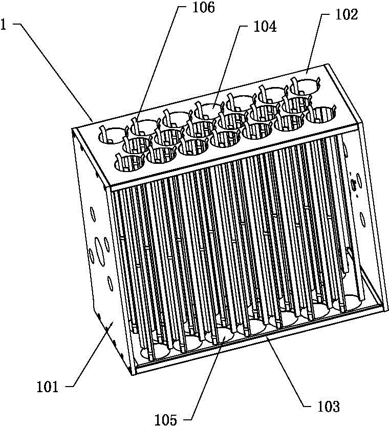
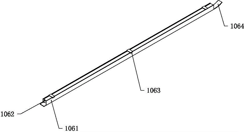
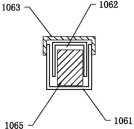
[0066] Such as figure 1 As shown, the multi-functional material receiving box 1 applied to the cup making machine in this embodiment is provided with multiple rows of material receiving units, each row of material receiving units includes a plurality of material receiving chambers, the number of rows of material receiving units and the number of each row of material receiving units. The number of the material receiving chambers of the material receiving unit can be set to different numbers according to actual needs. In this embodiment, the multifunctional material receiving box 1 is provided with three rows of material receiving units, and the material receiving chambers of two adjacent rows of material receiving units Staggered settings. Each material receiving chamber is provided with a material receiving port 104, a discharge port 105 and at least three evenly distributed elastic transmission limit rods 106, and each material receiving chamber is provided with a material r...

Embodiment 2

[0079] The main technical scheme of a multi-functional receiving box and shifting transmission device applied to a cup making machine in this embodiment is basically the same as that of Embodiment 1, and the features not explained in this embodiment are adopted in Embodiment 1. explanation, and will not repeat them here. The difference between this embodiment and Embodiment 1 lies in that the support plate 102 of the material inlet and the support plate 103 of the discharge port of this embodiment are fixedly connected with the box frame plates 101 on both sides, and are an integrally formed structure.

Embodiment 3

[0081] The main technical scheme of a multi-functional receiving box and shifting transmission device applied to a cup making machine in this embodiment is basically the same as that of Embodiment 1, and the features not explained in this embodiment are adopted in Embodiment 1. explanation, and will not repeat them here. In this embodiment, on the basis of Embodiment 1, a buffer brush is provided on the edge of the material receiving port 104. The function of the buffer brush is to buffer the plastic container, especially the lighter cover, directly falling into the material receiving limit channel. The buffer brush first Undertake a small amount of shallow-bottomed light-weight plastic containers. When the small stack of shallow-bottomed light-weight plastic containers reaches a certain weight, they will use their own weight to fall into the material-receiving limit channel, so as to ensure that the shallow-bottom light-weight plastic containers are in the material-receiving l...


PUM


Abstract

The invention discloses a multifunctional material receiving box applied to a cup making machine. The multifunctional material receiving box is provided with multiple rows of material receiving units, each row of material receiving units comprise a plurality of material receiving cavity cylinders, each material receiving cavity cylinder is provided with a material receiving opening, a material outlet and three elastic conveying limiting rods, therefore, stacking and counting of a whole row of plastic containers are realized, the problem that through a traditional cup making machine, number counting in stacking of a whole row of plastic containers is hard to realize is solved and meanwhile the stacked plastic containers can be unloaded to a next procedure conveniently. A material receiving device of the cup making machine comprises the material receiving box, a lifting device, a horizontal movement sliding device and a controller. The material receiving box is arranged on the horizontal movement sliding device in a slidable mode, a rotation driving device is installed on the horizontal movement sliding device and drives the material receiving box to rotate, and the horizontal movement sliding device is arranged on the lifting device in a liftable mode. The shift conveying device enables the material receiving box to move and drop to an appointed rotation station for unloading automation after completing material receiving at a material receiving station, and therefore production efficiency is improved.

Description

technical field [0001] The present invention relates to the technical field of stacking and packaging equipment (also called cup making machine, hereinafter referred to as "cup making machine") for plastic sheets to be thermoformed by a cup making machine, in particular to a multifunctional cup making machine Receiver and shift conveyor. Background technique [0002] At present, plastic sheets are thermoformed by a cup making machine into plastic containers, including cups, bowls, boxes and covers, etc., a plastic product used to hold or cover liquid or solid objects, commonly known as: "disposable plastic Cups", "disposable plastic bowls" and other containers, such plastic containers are widely used in all walks of life and in daily life, such as: beverages, yogurt, food cups, butter cups, jelly cups, disposable water cups, instant noodle bowls , ice cream cups or refrigerator food boxes, fast food bowl boxes and the lids of the above-mentioned various containers, etc., th...

Claims


Application Information

Patent Timeline
Patent Type & Authority Applications(China)
IPC IPC(8): B65D77/08B65G57/20B65G65/23
Inventor 王贤淮王昌佑
Owner GUANGDONG LONGXING PACKAGING IND
Why Eureka
Try Eureka