
Ball-locking type emergency repair leakage stoppage plate and method for repairing pipeline in emergency through ball-locking type emergency repair leakage stoppage plate

A plugging plate and ball lock technology, applied in the direction of pipe components, pipes/pipe joints/pipe fittings, mechanical equipment, etc., can solve the problem of less application, and achieve the effects of saving operating costs, good sealing performance, and good oil corrosion resistance

Active Publication Date: 2015-02-25
BEIJING GAS GRP
View PDF15 Cites 3 Cited by
  • Summary
  • Abstract
  • Description
  • Claims
  • Application Information

AI Technical Summary

Problems solved by technology

At present, the application of welded pressure plugging is less

Method used


Image

  • Ball-locking type emergency repair leakage stoppage plate and method for repairing pipeline in emergency through ball-locking type emergency repair leakage stoppage plate
  • Ball-locking type emergency repair leakage stoppage plate and method for repairing pipeline in emergency through ball-locking type emergency repair leakage stoppage plate
  • Ball-locking type emergency repair leakage stoppage plate and method for repairing pipeline in emergency through ball-locking type emergency repair leakage stoppage plate

Examples


Embodiment 1

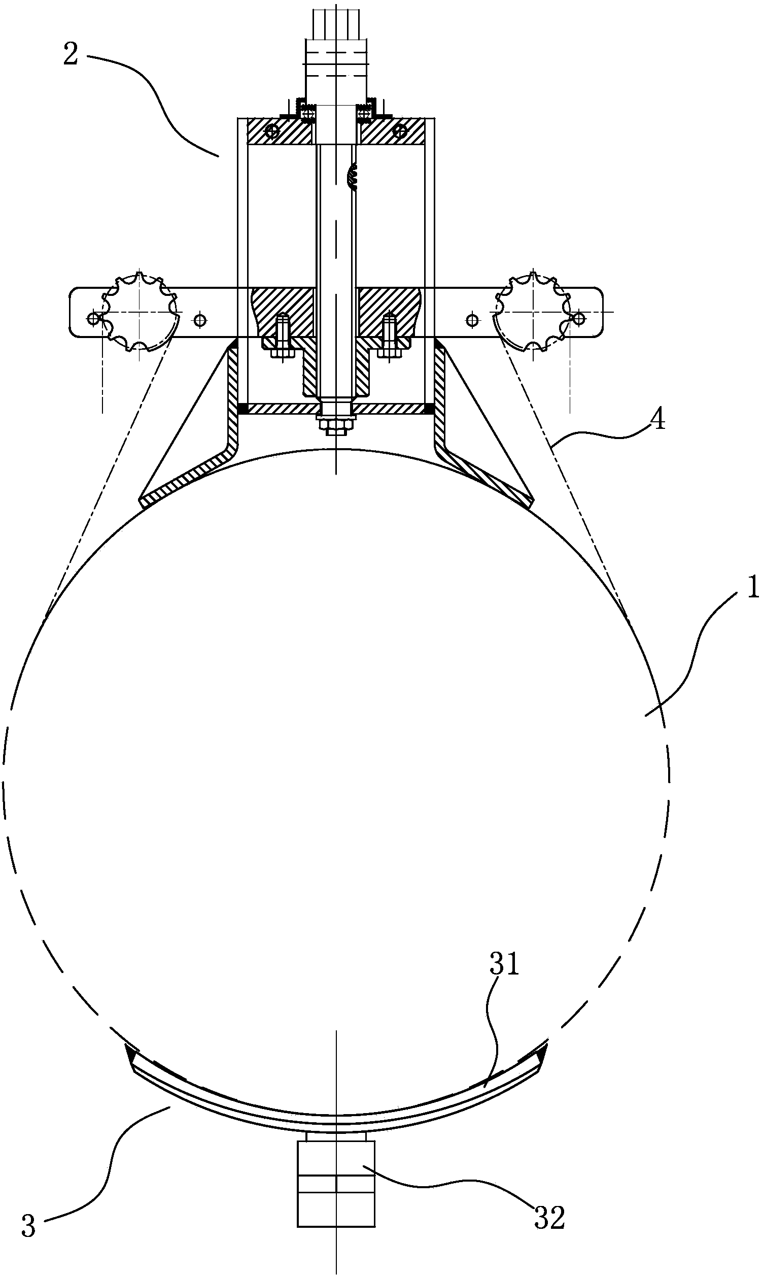
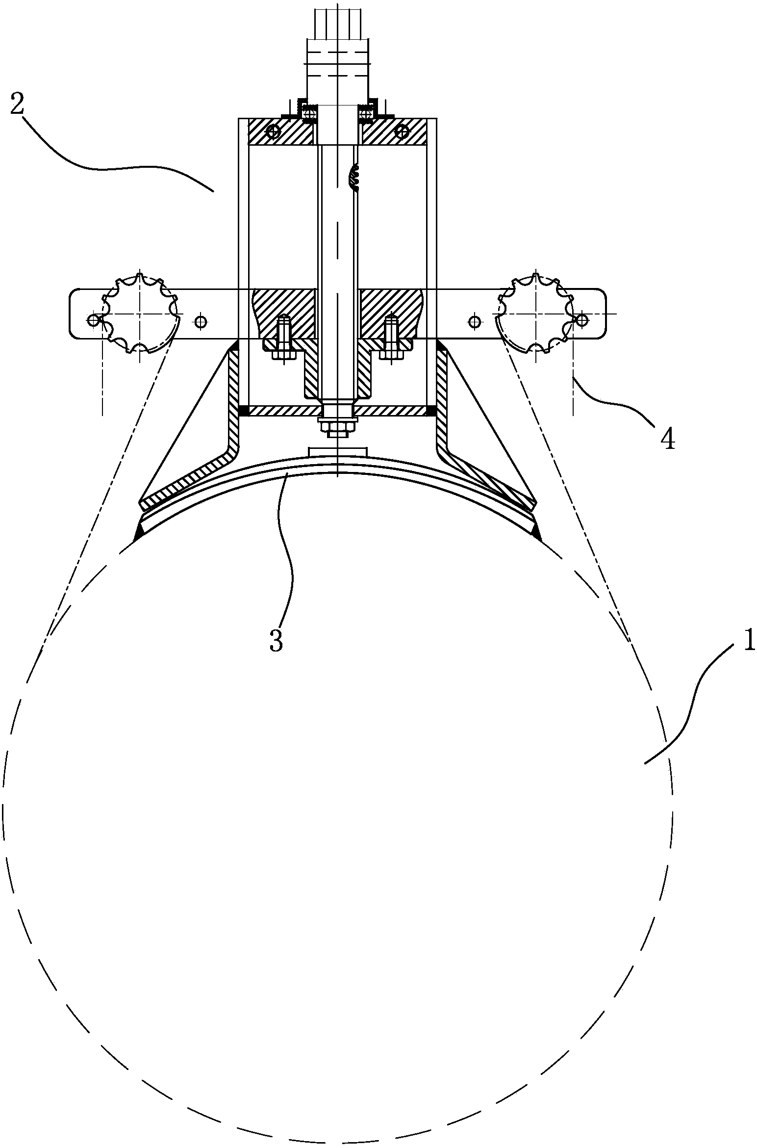
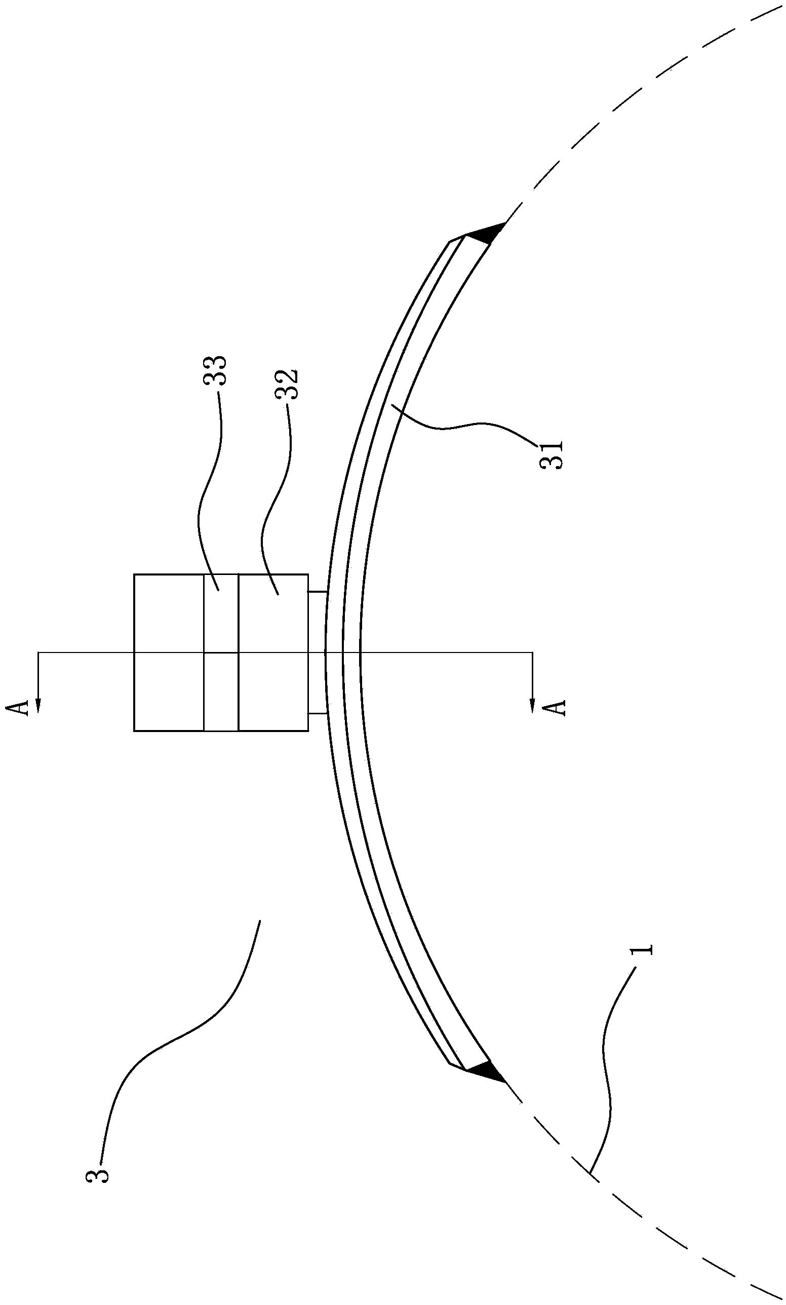
[0039] Such as Figure 1-7 shown, see Figure 4 , A ball-lock emergency repair plugging plate of the present invention includes a plate body 31 , a valve 32 and a sealing ball 321 . A vent hole is opened in the middle of the plate body 31 . A valve 32 is provided on the exhaust hole. The inner lower part of the valve 32 is a cylindrical hole, and the upper part is a circular platform hole. The circular platform hole is a circular platform hole with a small upper part and a larger lower part, and a sealing ball 321 is arranged in the valve 32 . The diameter of the sealing ball 321 is larger than the upper end of the circular table hole and smaller than the lower end of the circular table hole, and the sealing ball 321 is connected with the bottom of the valve 32 by a spring.

[0040] see Figure 4 , Figure 5 , The leak plugging plate 3 also includes an adapter 33 , a bolt 34 and a valve cap 35 . The top of the valve 32 is threadedly connected with an adapter 33 . The i...

Embodiment 2

[0054] A method for urgently repairing a pipeline with a ball-lock type leak plugging plate, comprising the following steps:

[0055] A. Thread the valve 32 of the plugging plate 3 to the adapter 33, and screw down the bolt 34 in the middle of the adapter 33, so that the bolt 34 pushes down the sealing ball 321 to open the ball lock;

[0056] B. Place the middle part of the plugging plate 3 on the leakage of the pipeline 1;

[0057] C. Connect the two sets of fixtures 2 with the plugging plate 3 at the same side of the leakage of the pipeline 1;

[0058] D. Fix both ends of the chain 4 with the fixture 2, and the fixture 2 fixes the leak-stopping plate through the chain groove of the leak-stopping plate 3;

[0059] E. The fixture 2 tightens the plugging plate 3 through the chain 4;

[0060] F. Weld with the pipe 1 along the outer edge of the plugging plate 3 that is not blocked by the fixture 2;

[0061]G. Remove the fixture 2, and weld the outer edge of the plugging plate ...


PUM


Abstract

The invention relates to a leakage stoppage plate, in particular to a ball-locking type emergency repair leakage stoppage plate and a method for repairing a pipeline in emergency through the ball-locking type emergency repair leakage stoppage plate. The ball-locking type emergency repair leakage stoppage plate is simple in structure, low in cost, easy and convenient to operate, long in service life, safe and reliable. The ball-locking type emergency repair leakage stoppage plate comprises a plate body (31), a valve (32) and a seal ball (321). An exhaust hole is formed in the middle of the plate body (31) and provided with the valve (32), a cylindrical hole is formed in the lower portion inside the valve (32), a big-end-down frustum-cone hole is formed in the upper portion inside the valve (32), the seal ball (321) is arranged inside the valve (32), the diameter of the seal ball (321) is larger than that of the upper end of the frustum-cone hole but smaller than that of the lower end of the frustum-cone hole, and the seal ball (321) is connected with the bottom of the valve (32) through a spring.

Description

technical field [0001] The invention relates to a leak-stopping board, in particular to a leak-stopping board used for leak-stopping of pipelines under pressure and a method for urgently repairing pipelines using the same. Background technique [0002] At present, the existing pressure plugging technology at home and abroad can be divided into two types according to the operation form: non-fired plugging and hot-fired plugging. [0003] According to different technical principles and methods, non-fire plugging can be divided into injection type plugging technology under pressure, bonding and sealing technology under pressure, top-tight sealing technology under pressure, etc. Non-fire plugging technology mainly refers to welding technology, which does not use open flames in the operation process, and has the advantages of safety, reliability, and easy operation. However, considering that the gas transmission and distribution pipelines are made of metal, the non-fired leakage...

Claims


Application Information

Patent Timeline
Patent Type & Authority Applications(China)
IPC IPC(8): F16L55/17
CPCF16L55/17
Inventor 颜丹平霍志刚张海梁赵欣陈文利韩赞东钱迪高岷
Owner BEIJING GAS GRP
Learn More