A magnetic tweezers and optical tweezers measurement and control system

A technology of measurement and control system and magnetic tweezers, applied in the microscopic field, can solve problems such as unrealizable, non-rotating, easy to burn, etc.

Active Publication Date: 2017-02-15
HUAZHONG UNIV OF SCI & TECH
View PDF4 Cites 0 Cited by
  • Summary
  • Abstract
  • Description
  • Claims
  • Application Information

AI Technical Summary

Problems solved by technology

The two technologies have their own advantages and disadvantages. For example, the optical tweezers have a large force, cannot rotate, and are easy to burn the sample, while the magnetic tweezers are the opposite. The two technologies are complementary
[0003] Single-molecule manipulation equipment has achieved the control and research of a single molecule, but it is impossible to accurately control and measure two or more different molecules at the same time, as well as the reactions or interactions between them.

Method used


Image

  • A magnetic tweezers and optical tweezers measurement and control system
  • A magnetic tweezers and optical tweezers measurement and control system
  • A magnetic tweezers and optical tweezers measurement and control system

Examples


Embodiment 1

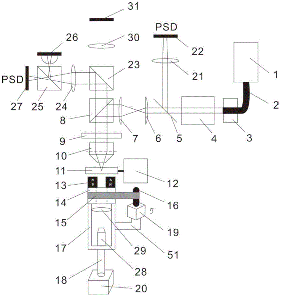
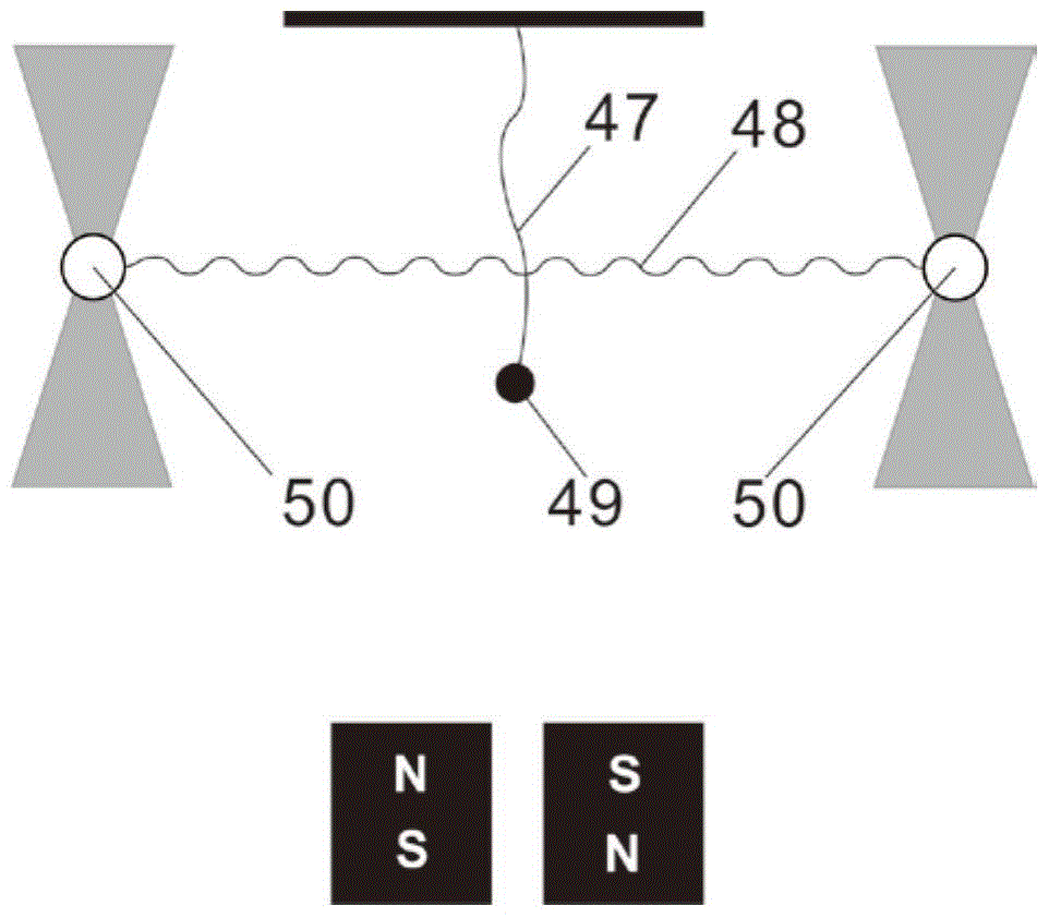
[0021] see figure 1 , a magnetic tweezers and optical tweezers measurement and control system provided in an embodiment of the present invention is used to control the first experimental molecule 47 connected to the surface of the magnetic ball 49 and the second experimental molecule 47 bound to the surface of the microbead 50 in the experimental solution. Molecule 48, the experimental solution includes a solution of microbeads 50, a solution containing the second experimental molecule 48, and an experimental buffer; it is characterized in that the measurement and control system includes:

[0022] The sample pool 11, the first experimental molecule 47 connected to the surface of the magnetic ball 49 and the second experimental molecule 48 bound to the surface of the microbead 50 are arranged in the sample pool 11;

[0023] A sample action device, the sample action device is connected to the sample pool 11, the sample action device drives the sample pool 11 to move, and is used...

Embodiment 2

[0046] In order to introduce the embodiment of the present invention more clearly, the following introduces it from the usage method of the embodiment of the present invention.

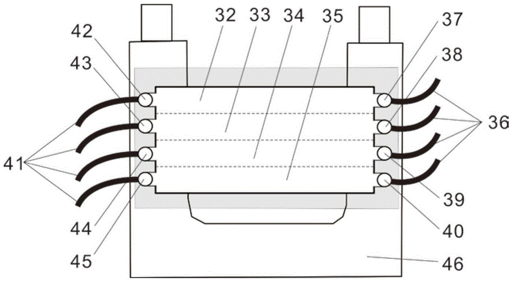
[0047] Firstly, the top of the fourth laminar flow channel 35 is treated, such as making it coated with digoxin antibody molecules. Next, the sample cell 11 is assembled into the system. Open the first liquid inlet 37, the second liquid inlet 38, the third liquid inlet 39 and the fourth liquid inlet 40 and the first liquid outlet 42, the second liquid outlet 43, the third liquid outlet 44 that is The valve of the fourth liquid outlet 45 applies hydraulic pressure to inject the solution containing microbeads 50 , the solution containing the second test molecule 48 , the buffer solution and the solution containing magnetic balls respectively at a slow speed. Wherein, the surface of the microbead and the two ends of the second experimental molecule 48 have been treated so that they can be combined toget...


PUM


Abstract

The invention discloses a magnetic tweezers and optical tweezers measuring and controlling system, belonging to the technical field of microscopy. The magnetic tweezers and optical tweezers measuring and controlling system comprises a sample movement device, wherein the sample movement device is connected with a sample tank; a laser emission device is used for emitting laser; the laser emitted by the laser emission device is irradiated into the sample tank; the laser is irradiated to microparticles or microspheres by a laser microscopic device; a laser monitoring device is used for receiving the laser emitted by the laser emission device and an image in the sample tank is photographed by a visible light imaging device; a central controller is connected with the laser monitoring device; a central processing unit is connected with the visible light imaging device and is connected with the sample movement device; and the central processing unit is connected with a magnetic tweezers device and is connected with the laser emission device. The magnetic tweezers and optical tweezers measuring and controlling system can be used for simultaneously controlling two different molecules by an optical trap and magnetic tweezers, and has great degree of freedom, great force range and high accuracy.

Description

technical field [0001] The invention relates to the field of microscopic technology, in particular to a measurement and control system for magnetic tweezers and optical tweezers. Background technique [0002] In the past 20 to 30 years, people have made brilliant achievements in the field of single-molecule microscopy, and single-molecule microscopy instruments have been continuously improved. For example, the 2014 Nobel Prize in Chemistry was awarded to single-molecule microscopy. At present, the commonly used single-molecule microscopic measurement and control instruments include optical tweezers and magnetic tweezers. The measurement and control of the two are very precise, and there is no direct contact or damage to the sample. Among them, optical tweezers are optical potential wells formed by passing a laser beam through transparent particles, and the experimental target can be moved by moving the laser beam. Magnetic tweezers fix one end of the molecule, connect the o...

Claims


Application Information

Patent Timeline
Patent Type & Authority Patents(China)
IPC IPC(8): G01N21/01
Inventor 肖波涛符青山
Owner HUAZHONG UNIV OF SCI & TECH
Why Eureka
Try Eureka