
Method for quick measurement of remnant magnetic moment and inductive magnetic moment of tested object in terrestrial magnetic field

A technology of geomagnetic field and geomagnetic orientation method, which is applied to the magnetic moment measurement system of magnetic objects, the field of residual magnetic moment and magnetic induction moment measurement, can solve the problems of reduced accuracy, complex data processing, cumbersome test operation, etc., and achieve accurate and fast measurement Effect

Inactive Publication Date: 2015-02-25
BEIJING INST OF SPACECRAFT ENVIRONMENT ENG
View PDF3 Cites 8 Cited by
  • Summary
  • Abstract
  • Description
  • Claims
  • Application Information

AI Technical Summary

Problems solved by technology

The method used in my country to test the magnetic moment of spacecraft in the geomagnetic environment is the combination of the equatorial drawing method and the geomagnetic orientation method. Only one direction of the moment is directly measured by the equatorial drawing method, and the residual magnetic moments in the other two directions are calculated by the geomagnetic orientation method, and the accuracy will be reduced

Method used


Image

  • Method for quick measurement of remnant magnetic moment and inductive magnetic moment of tested object in terrestrial magnetic field
  • Method for quick measurement of remnant magnetic moment and inductive magnetic moment of tested object in terrestrial magnetic field
  • Method for quick measurement of remnant magnetic moment and inductive magnetic moment of tested object in terrestrial magnetic field

Examples


Embodiment Construction

[0025] The following introduces the specific implementation mode as the content of the present invention, and the content of the present invention will be further clarified through the specific implementation mode below. Of course, the following specific embodiments are described only to illustrate different aspects of the present invention, and should not be construed as limiting the scope of the present invention.

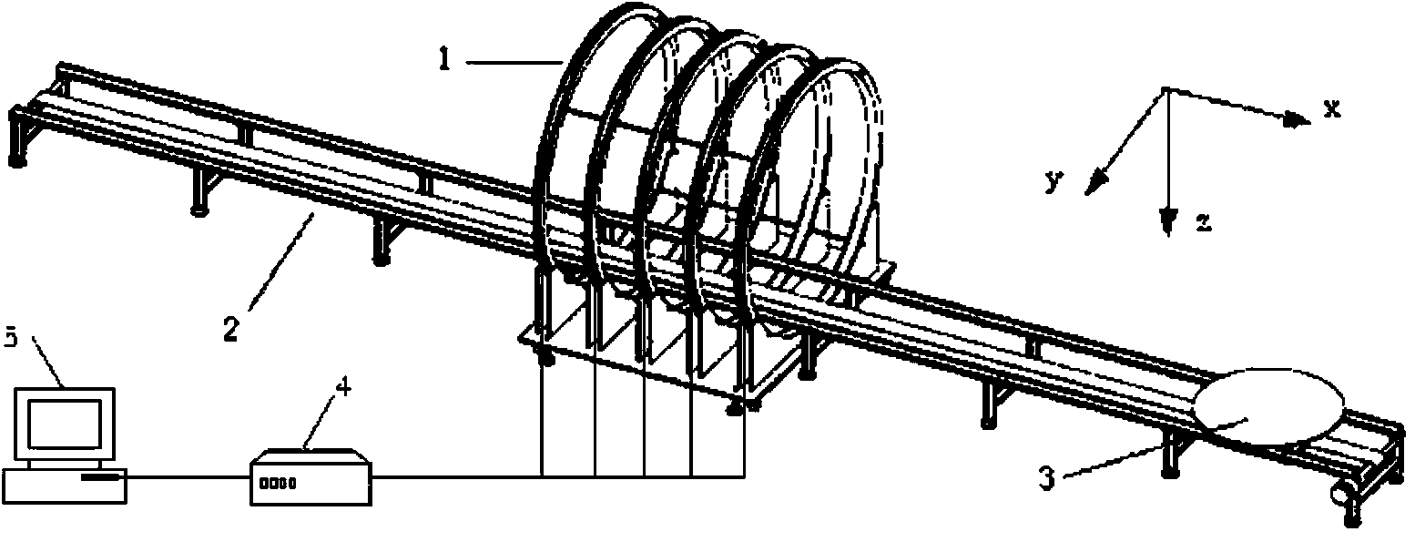
[0026] figure 1 It is a schematic diagram of the main structure of the magnetic moment measurement system of the magnetic flux method of the present invention. The measurement system measures the magnetic moment of the spacecraft through the combination of the magnetic flux method and the geomagnetic orientation method. The self-rotating turntable 3 is used to support the spacecraft and make the spacecraft rotate around it to measure the magnetic moment of the spacecraft. The center of the guide rail 2 is provided with five sets of vertical magnets arranged in pa...


PUM


Abstract

The invention discloses a system for quick measurement of the magnetic moment of a spacecraft in a terrestrial magnetic field. According to the system, the magnetic moment of the spacecraft is measured through the combination of the magnetic flux method and the terrestrial magnetic orientation method. The system comprises a lengthwise guide rail and a rotary table capable of achieving autogiration and arranged on the guide rail in a sliding mode, wherein the rotary table is used for supporting the spacecraft and enabling the spacecraft to rotate around the rotary table for measurement of the magnetic moment of the spacecraft, five vertical magnetic flux induction coils are arranged in the middle of the guide rail in parallel and are supported by a supporting device, the guide rail penetrates through the five magnetic flux induction coils to enable the rotary table to penetrate through the centre of the magnetic flux induction coils in a sliding mode, and the five magnetic flux induction coils are electrically connected with a fluxmeter through wires respectively to transmit a measured magnetic flux signal to a data processing system through the fluxmeter. The invention further discloses a method for quick measurement of the magnetic moment by means of the system. When the magnetic moment of the spacecraft is measured through the combination of the magnetic flux method and the terrestrial magnetic orientation method, the spacecraft magnetic moment measurement period is shortened, real magnetic moment in two directions can be measured, and testing precision is improved.

Description

technical field [0001] The invention belongs to the technical field of magnetic measurement in spacecraft magnetic tests, and in particular relates to a system for measuring the magnetic moment of a magnetic object under the earth's magnetic field and a method for measuring the residual magnetic moment and the magnetic induction moment by using the system. Background technique [0002] The research on magnetic moment measurement technology (mainly measuring residual magnetic moment) is an important part of spacecraft magnetic test technology research. Magnetic moment measurements in the Earth's magnetic field are required when large zero-field simulation facilities are not available. Due to the magnetization of the earth's magnetic field, the spacecraft will generate an induced magnetic moment. In order to obtain the remanent magnetic moment of the spacecraft, it is necessary to use a certain The algorithm separates the remanence and induction moments. [0003] At present,...

Claims


Application Information

Patent Timeline
IPC IPC(8): G01R33/12
Inventor 刘超波肖琦孟立飞王斌代佳龙董宜煊
Owner BEIJING INST OF SPACECRAFT ENVIRONMENT ENG
Learn More