Millimeter wave imaging method and system

A millimeter wave imaging and imaging system technology, applied in radio wave measurement systems, electromagnetic wave detection, radio wave reflection/re-radiation, etc., can solve the problems of slow imaging, insufficient imaging capability, and low real-time millimeter wave imaging, etc. achieve the effect of improving efficiency

Inactive Publication Date: 2015-02-25
SHENZHEN & INVESTMENT HLDG GRP
View PDF5 Cites 21 Cited by
  • Summary
  • Abstract
  • Description
  • Claims
  • Application Information

AI Technical Summary

Problems solved by technology

[0003] The technical problem solved by the present invention is to construct a millimeter-wave imaging method and system to overcome the technical problems of the prior art that the millimeter-wave imaging has low real-time performance, insufficient imaging capability, and slow imaging

Method used


Image

  • Millimeter wave imaging method and system

Examples


Embodiment Construction

[0018] The technical solutions of the present invention will be further described below in conjunction with specific embodiments.

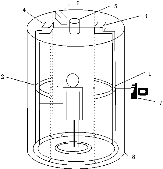
[0019] Such as figure 1 As shown, the specific embodiment of the present invention is to provide a millimeter-wave imaging method. The imaging system includes: a first millimeter-wave antenna array 1 and a second millimeter-wave antenna array 2 that are oppositely arranged in an arc shape, and the first millimeter-wave antenna array 2 The millimeter-wave antenna array 1 and the second millimeter-wave antenna array 2 are respectively formed by multiple pairs of antenna units arranged in an arc distribution, and the antenna units include transmitting antennas and receiving antennas. The transmitting antenna and the receiving antenna can be arranged side by side horizontally, or can be arranged side by side vertically. In a specific embodiment, a control module 6 for controlling the operation of the antenna array is included. The millimeter-wave im...


PUM


Abstract

The invention relates to a millimeter wave imaging method and system. A first millimeter wave antenna array and a second millimeter wave antenna array transmit continuous frequency waves to an arc middle area and receive returned millimeter waves. The first millimeter wave antenna array and the second millimeter wave antenna array move in the vertical direction so as to transmit and receive the millimeter waves in the vertical direction of the arc middle area. An image processing module carries out image combination on the millimeter waves received by a first millimeter wave receiving and transmitting module and a second millimeter wave receiving and transmitting module so that a three-dimensional image of an objected to be imaged can be formed in the arc middle area. According to the millimeter wave imaging method and system, a detecting mode of combining translation scanning of vertical mechanical driving of switch antenna arrays and arc direction scanning is adopted, all-dimensional scanning of the human body can be effectively finished, and the safety inspection efficiency is improved.

Description

technical field [0001] The present invention relates to a millimeter wave imaging method and system, in particular to a millimeter wave imaging method and system capable of rapidly performing millimeter wave imaging. Background technique [0002] The ever-increasing security risks in today's world make it imperative to detect potentially dangerous goods quickly and effectively. Airport security check areas need to conduct security checks on a large number of people in order to find dangerous goods of various shapes. In the past, metal security gates were sufficient to detect dangerous goods. Today, these hazards may be made of a variety of materials including metals and non-metals. These dangerous goods may include powders, plastics, ceramics, liquids, gels, and very thin flakes and bulk explosives, and metal security doors are helpless for these dangerous goods. New types of dangerous goods that pose a threat to global aviation safety are becoming more and more comple...

Claims


Application Information

Patent Timeline
Patent Type & Authority Applications(China)
IPC IPC(8): G01S13/90G01V3/12
CPCG01S13/90G01V3/12G01S13/887G01S13/9088
Inventor 黄继宏
Owner SHENZHEN & INVESTMENT HLDG GRP
Why Eureka
Try Eureka