Determination Method for a Position Signal

a position signal and determination method technology, applied in the direction of instruments, digital computer details, transmission, etc., can solve the problems of fine correction methods described there only working satisfactorily, subject to errors, and inability to measure signals x, y,

Inactive Publication Date: 2007-12-13
SIEMENS AG
View PDF6 Cites 16 Cited by
  • Summary
  • Abstract
  • Description
  • Claims
  • Application Information

AI Technical Summary

Benefits of technology

[0023] An object of the present invention consists in specifying a method which is as simple as possible to carry out, giving as compl

Problems solved by technology

In practice, however, the measuring signals x, y are not ideal, but subject to error.
However, the fine correcti

Method used


Image

  • Determination Method for a Position Signal
  • Determination Method for a Position Signal
  • Determination Method for a Position Signal

Examples


Embodiment Construction

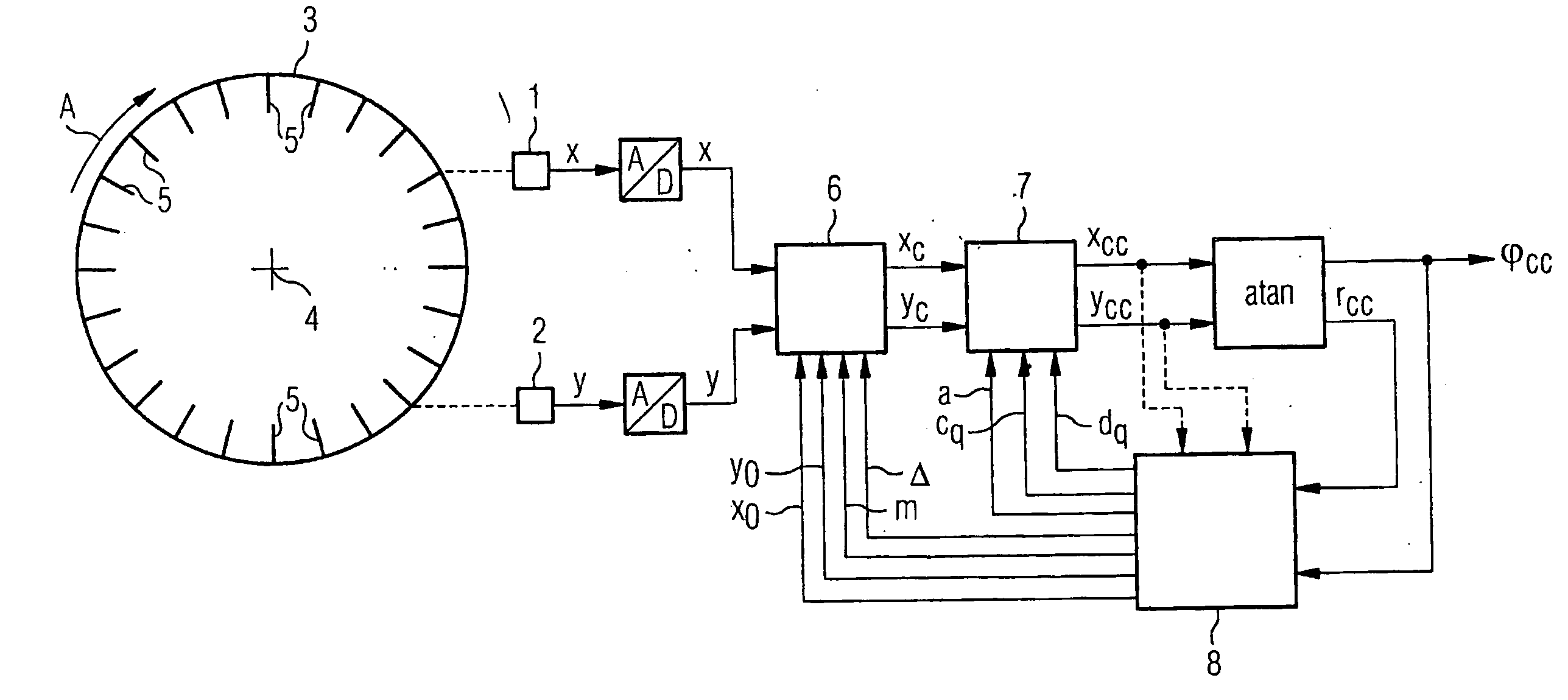
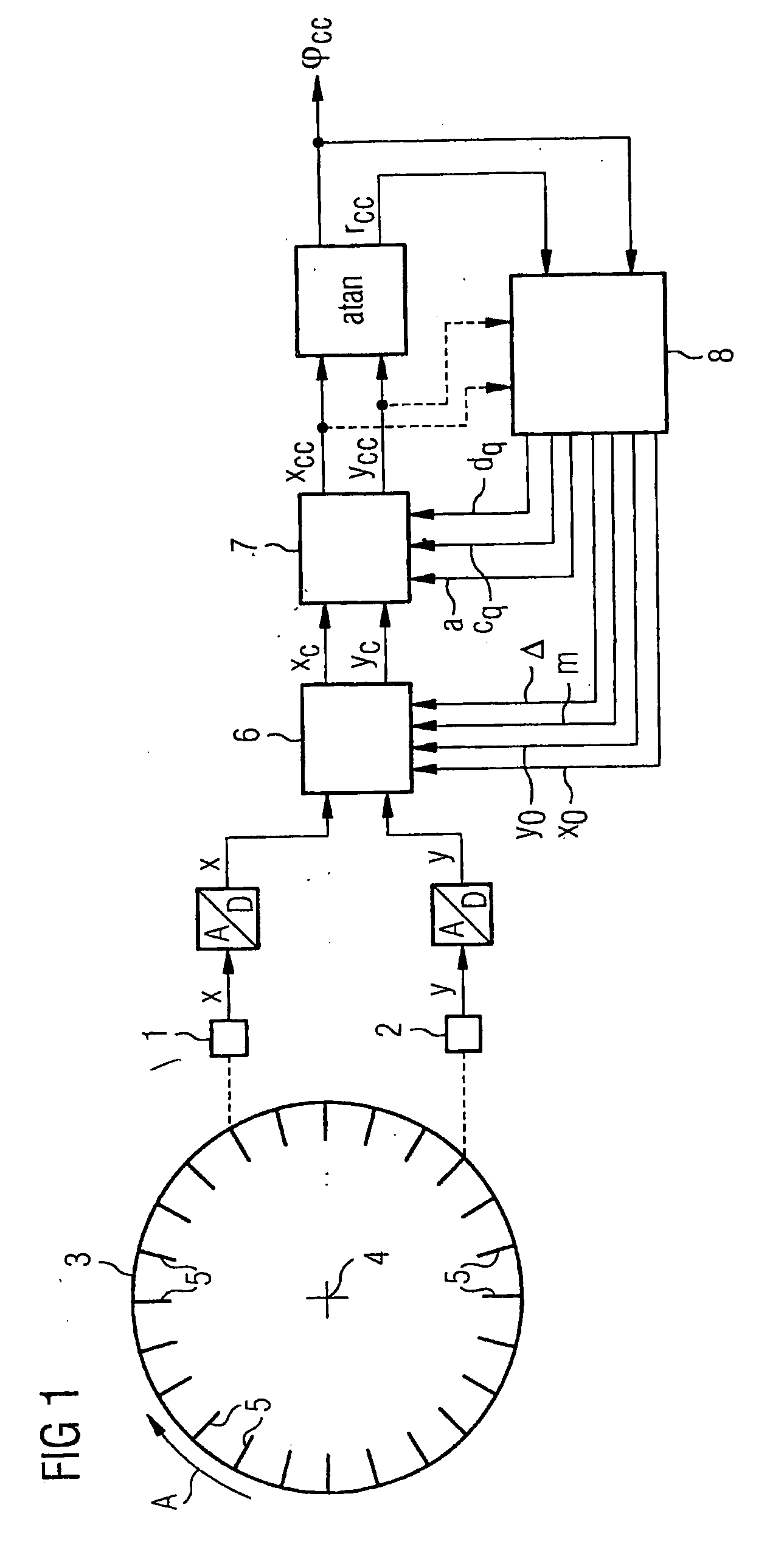
[0058] As shown in FIG. 1, a determination circuit, by means of which a position signal φcc is to be determined, has two sensors 1, 2 and a measuring scale 3. The measuring scale 3 is moveable relative to the sensors 1, 2. As shown in FIG. 1, it can for example be rotated about an axis of rotation 4. This is indicated in FIG. 1 by an arrow A. The measuring scale 3 has numerous (e.g. 1000 to 5000) equally-spaced scale divisions 5. The sensors 1, 2 scan the measuring scale 3 and thereby supply corresponding measuring signals x, y.

[0059] In the ideal case, the sensors 1, 2 have exactly equal sensitivities, and are ideally positioned. For a uniform movement of the measuring scale 3 relative to the sensors 1, 2, the latter are therefore in a position to supply measuring signals x, y which satisfy the following conditions:

[0060] They are periodic.

[0061] They have an equal amplitude.

[0062] They are exactly sinusoidal.

[0063] They have a phase offset relative to each other of exactly 90...


PUM


Abstract

Two sensors scan a measuring scale, which can be displaced in relation to the sensors and comprises a plurality of equidistant measuring gradation, and deliver corresponding measuring signals. The measuring signals are periodic during a uniform relative displacement of the measuring scale, essentially sinusoidal and essentially phase-shifted by 90° in relation to one another. They have an essentially identical amplitude and a base frequency that corresponds to the relative displacement of the measuring scale. During a delivery period of measuring signals, the measuring scale carries out a relative displacement through one measuring gradation. Corrected signals are determined from the measuring signals using correction values. A signal of the position of the measuring scale in relation to the sensors is determined in turn using said correction signals. Fourier coefficients are determined in relation to the base frequency for the corrected signals or for at least one supplementary signal that is derived from the corrected signals, said coefficients being used in turn to update the correction values. Said correction values contain two shift correction values at least one amplitude correction value and at least one phase correction value for the measuring signals, or part of said values, in addition to at least one correction value for at least one higher frequency wave of the measuring signals.

Description

CROSS REFERENCE TO RELATED APPLICATIONS [0001] This application is the US National Stage of International Application No. PCT / EP2005 / 053681, filed Jul. 28, 2005 and claims the benefit thereof. The International Application claims the benefits of German application No. 10 2004 038 621.8 DE filed Aug. 9, 2004, both of the applications are incorporated by reference herein in their entirety.FIELD OF INVENTION [0002] The present invention relates to a determination method for a position signal, with which [0003] two sensors scan a measuring scale which is moveable relative to the sensors, and has a plurality of equally-spaced scale divisions and thereby supply corresponding measuring signals, [0004] for a uniform relative movement of the measuring scale the measuring signals are periodic, are essentially sinusoidal, have essentially the same amplitude, have a phase offset relative to one another which is essentially 90°, have a basic frequency which corresponds essentially with the relat...

Claims


Application Information

Patent Timeline
IPC IPC(8): G01D18/00
CPCG01D5/24495G01D5/2448
Inventor FINKLER, ROLANDKOPKEN, HANS-GEORG
Owner SIEMENS AG
Why Eureka
Try Eureka