Generation method and device for flight plans in earthquake emergency aerial remote sensing

A technology of flight planning and aviation remote sensing, applied in the field of remote sensing communication, which can solve the problems of waste of flight time, inability to formulate flight plans, and reduce the timeliness of emergency aviation remote sensing flights, etc.

Inactive Publication Date: 2015-02-25
INST OF REMOTE SENSING & DIGITAL EARTH CHINESE ACADEMY OF SCI
View PDF3 Cites 3 Cited by
  • Summary
  • Abstract
  • Description
  • Claims
  • Application Information

AI Technical Summary

Problems solved by technology

[0004] However, for earthquake emergency aerial remote sensing, there is no special operation process at present, and it is difficult to meet many requirements of post-earthquake emergency flight response by using conventional aerial remote sensing operations: there is no definite flight area range and ground resolution, and in this case it will not be possible to Make a flight plan; if you directly set the flight range centered on the epicenter and use the traditional "south-north" or "east-west" flight, it is likely to miss the severely affected areas and waste precious flight time in unimportant places. In this way, the timeliness of emergency aviation remote sensing flight is reduced, and the emergency effect is greatly reduced; if the flight is carried out according to the administrative area and traffic elements, it may be because there are too many administrative areas in the area and the traffic elements are too long, but not all administrative areas or Traffic elements all have the same possibility of being affected by disasters, and it is easy to cause the planned flight distance to be too long. Therefore, it is impossible to carry out remote sensing flights targeted at key areas that may be severely affected.
[0005] For the problem of poor timeliness of traditional flight methods in earthquake emergency aerial remote sensing, no effective solution has been proposed so far

Method used


Image

  • Generation method and device for flight plans in earthquake emergency aerial remote sensing
  • Generation method and device for flight plans in earthquake emergency aerial remote sensing

Examples


Embodiment Construction

[0018] The present invention will be described in further detail below through specific embodiments and in conjunction with the accompanying drawings.

[0019] In order to improve the timeliness of rescue in earthquake emergency aerial remote sensing, embodiments of the present invention provide a method and device for generating a flight plan in earthquake emergency aerial remote sensing.

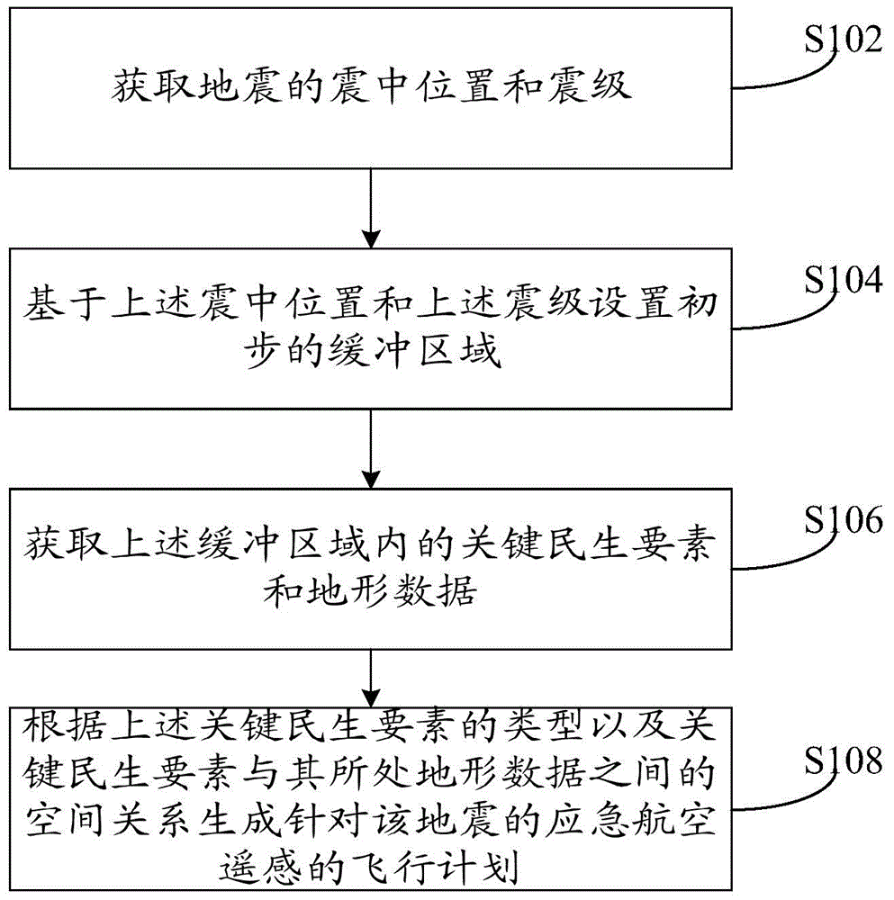
[0020] see figure 1 The flow chart of the generation method of the flight plan in the earthquake emergency aerial remote sensing shown, the method includes the following steps:

[0021] Step S102, acquiring the epicenter location and magnitude of the earthquake.

[0022] Step S104, setting a preliminary buffer zone based on the above-mentioned epicenter location and the above-mentioned magnitude. For example: take the epicenter position as the center of the circle, and set the length corresponding to the magnitude as the radius to make a circle, and set the area covered by the circle as ...


PUM


Abstract

The invention provides a generation method and device for flight plans in earthquake emergency aerial remote sensing. The method includes: acquiring epicentral position and magnitude of an earthquake; setting a preliminary buffer area on the basis of the epicentral position and magnitude; acquiring key people's life elements and topographic data in the buffer area, wherein the key people's life elements include at least one of basic geographic data, administrative region vector data, road data and water system data; generating the flight plans of emergency aerial remote sensing for the earthquake according to types of the key people's life elements and the spatial relationship between the key people's life elements and the topographic data, wherein the flight plans include flight area coverage and flight lines. By the method and device, existing resources can be utilized to the utmost extent, remote sensing image data of severely afflicted areas are acquired, flight time is fully utilized, and accordingly effective rescue is carried out beneficially.

Description

technical field [0001] The invention relates to the field of remote sensing communication, in particular to a method and device for generating a flight plan in earthquake emergency aviation remote sensing. Background technique [0002] For a long time, due to the limitation of the development of science and technology, the most important and urgent problem that people face after the earthquake is the lack of information on the disaster area. Due to the lack of information on the disaster situation, the relevant departments directly cannot achieve accurate and timely disaster assessment when assessing the disaster area; at the same time, it is difficult to be targeted when mobilizing, deploying, and distributing disaster relief forces, seriously affecting every second. disaster relief work. Since the beginning of this century, aerial remote sensing technology has been developed unprecedentedly, which provides a technical possibility for solving the above problems. Aerial re...

Claims


Application Information

Patent Timeline
IPC IPC(8): G08G5/00
CPCG08G5/0056
Inventor 谭骏翔左正立赵海涛邱文毕建涛
Owner INST OF REMOTE SENSING & DIGITAL EARTH CHINESE ACADEMY OF SCI
Why Eureka
Try Eureka