
Aerosol spray generation

An aerosol and spray chamber technology, applied in the field of generating aerosol spray, can solve problems such as the sound quality or acoustics of aerosol spray that have not been proposed

Active Publication Date: 2018-05-25
UNILEVER IP HLDG BV
View PDF7 Cites 0 Cited by
  • Summary
  • Abstract
  • Description
  • Claims
  • Application Information

AI Technical Summary

Problems solved by technology

Few of these publications suggest methods by which the sound quality or acoustics produced by the aerosol spray can be controlled

Method used


Image

  • Aerosol spray generation
  • Aerosol spray generation
  • Aerosol spray generation

Examples


Embodiment Construction

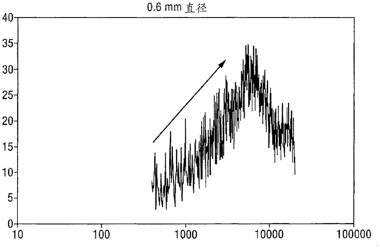
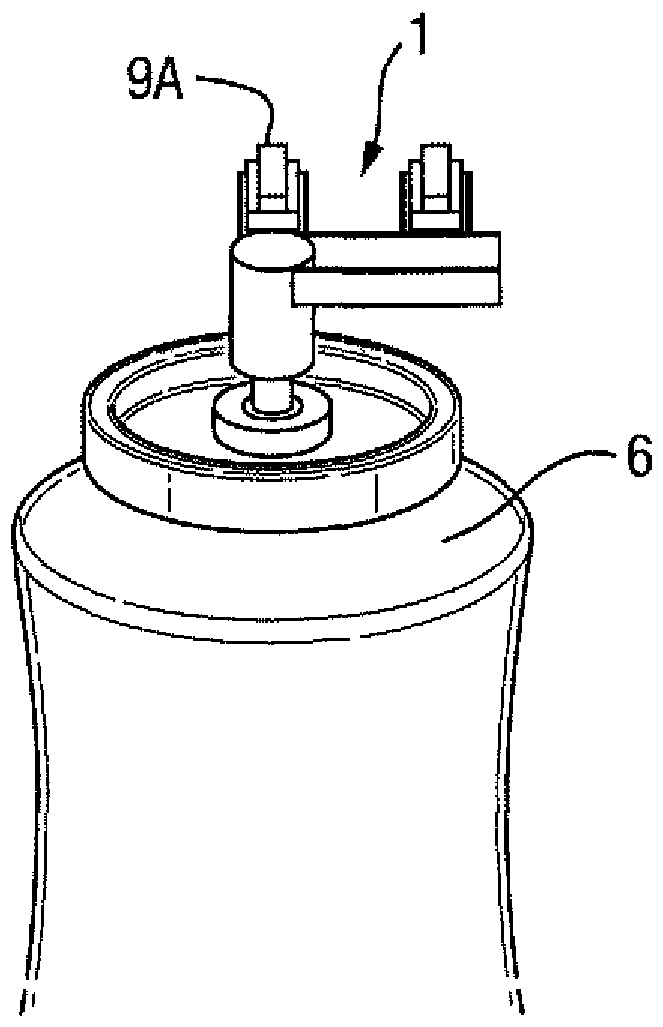
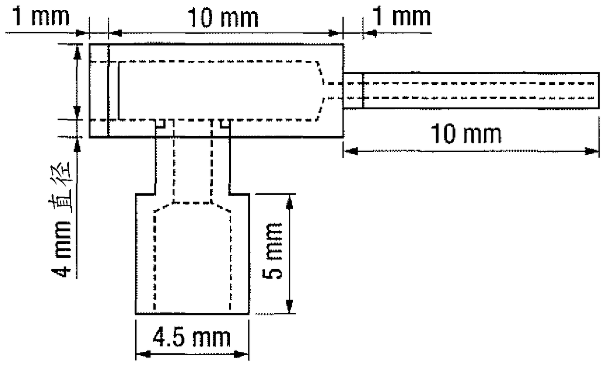
[0060] In the first series of experiments, a number of spray line components were evaluated. Figures 1 to 4 show the structural arrangements used. The part fits in the groove 7 of the aluminum "panel" 1 and consists of an upper half 4 and a lower half 5 which in turn is connected to a commercially available antiperspirant aerosol product 6 (175 ml Dove TM Antiperspirant spray aerosol, spray down to 75% fill level before use). The screed rests on the valve stem of the aerosol bottle 6 so that downward pressure on the screed 1 causes the valve to open and allow release of the pressurized contents therein. The valve stem is loaded into the template 1 through a channel 8 in the underside of chamber 9 of the template 1 which is connected to the first section 2A or 2B of the spray pipe (see Figure 1A and 1B ) in fluid communication. The first section of the spray conduit 2A or 2B is held in close proximity and in fluid communication with the second (terminal) section 3 of the sp...


PUM


Abstract

A method and product for producing a soft and sounding aerosol spray from a particulate suspension, said method and product relating to a spray duct having a discharge orifice with an internal diameter of 0.5 to 0.8 mm and a channel leading to the internal diameter of 0.5 mm A spray pipe terminal segment having a length of 5 mm or more to a discharge hole of 0.8 mm that includes the discharge hole and has an unobstructed tubular inner surface.

Description

technical field [0001] The present invention relates to a method for producing an aerosol spray and a product for doing so. In particular, the present invention relates to methods of producing an aerosol spray from the dispersion of microparticles. Background technique [0002] Numerous publications disclose the generation of aerosol sprays. Few of these publications suggest methods by which the sound quality or acoustics produced by the aerosol spray can be controlled. [0003] US 3,872,605 (Carborundum, Inc., 1976) discloses a muffler device for reducing the noise generated by compressed air or compressed air-particulate mixtures. The muffler has a generally constant diameter hole that is moderately larger than the nozzle hole for which the muffler is designed. The minimum diameter of the disclosed nozzle hole is 3 / 8 inch, which equals approximately 9.5 millimeters. [0004] US 5,929,396 (Ewad, 1999) discloses a noise reducing diffuser comprising an elongated housing w...

Claims


Application Information

Patent Timeline
Patent Type & Authority Patents(China)
IPC IPC(8): B65D83/20A61K8/04B05B1/00B65D83/14B65D83/68
CPCA61K8/0241A61K8/046A61Q15/00B05B1/00B65D83/20B65D83/753B65D83/68A61K2800/412A61K2800/87B05B1/002B65D83/30B65D83/752
Inventor N.J.范迪克L.格兰杰A.莫雷塔B.P.纽比S.A.沃森
Owner UNILEVER IP HLDG BV
Learn More